


Bar Code Scanner Specifications for XL200 Controllers
Scanner Specifications
Any scanner connected to an XL200 series controller must conform to the following communication specifications:
- Baud Rate: 9600
- Stop Bits: 1
- Parity: None
- Data Bits: 8
- Suffix: None (some scanners append a carriage return at the end of every scan by default)
DB9 Port
The DB9 port on the top of the XL200 controller has three uses:
- Scanner port
- Debug port
- Flash memory port
DB9 Port Pinout
| 2 | RS232 TX |
| 3 | RS232 RX |
| 5 | GND |
| 7 | RS232 CTS |
| 8 | RS232 RTS |
Pin 7
Pin 7 of the DB9 port is the Clear-to-Send input on the controller.
A pull up resistor on that input keeps it high. In some RS232 applications, this input is toggled by the outside device’s Request-to-Send (called handshaking).
The XL200 controller does no handshaking, with either hardware or software, so it doesn’t use pin 7 when communicating with other devices. However, a laptop connected to that port usually pulls pin 7 “low,” which informs the controller to set up the port for a debug/flash.
Note: Make sure the scanner is configured so that it does not pull pin 7 low. If the scanner pulls pin 7 low for any reason, the controller will not configure itself for a scanner. The input is retested on every power up.
Note: The scanner should be setup so that its ground matches the AMS ground, and its TX goes to the AMS RX. No other connections are necessary for scanner communication.
Zebra LI3608 Bar Code Scanner Setup
Note: The following setup procedure works only with the Zebra LI3608 bar code scanner. For other bar code scanners, please contact the manufacturer for proper setup procedures.
When a Zebra LI3608 bar code scanner is connected to an XL200 series controller for the first time, the scanner must be set up to properly communicate with the controller before it can be used for data entry.
Setup Procedure
- Turn on the scanner. The scanner plays a musical tone, indicating it is on.
- Verify that the power light on the power supply is on.
- Turn off the XL200 series controller, but leave the scanner turned on.
- Scan the bar code below. Do not proceed to the next bar code until you hear a beep confirming the scanner has read the bar code.
- Once the bar codes are read, the setup is complete and the scanner is ready for operation.
- Turn the XL200 series controller on.
Note: This particular scanner doesn’t have the capability of turning off the “RTS/CTS” (pin 7 and pin 8) signal as described earlier, so pin 7 and pin 8 of the DB9 connector MUST be clipped or removed for proper operation of the scanner. See the troubleshooting section for more details.

Symbol DS3408 and LS3408 Bar Code Scanner Setup
Note: The following setup procedure works only with the Symbol DS3408 and LS3408 bar code scanner. For other bar code scanners, please contact the manufacturer for proper setup procedures.
When a Symbol DS3408 or LS3408 bar code scanner is connected to an XL200 series controller for the first time, the scanner must be set up to properly communicate with the controller before it can be used for data entry.
Setup Procedure
- Turn on the scanner. The scanner plays a musical tone, indicating it is on.
- Turn off the XL200 series controller, but leave the scanner turned on.
- For wireless scanners, use the scanner to scan the wireless base first. Failing to do this will prevent the bar code scanner from functioning properly.
- Scan this bar code:

When the scanner successfully scans the bar code, it beeps.
- Turn on the controller.
a. If the scanner makes any sound while the controller boots, you must repeat the scanner setup process.
b. If the scanner remains silent while the controller boots, the scanner is successfully setup.
Sick IDM160-300S/411S or IDM260 (2D) Corded Bar Code Scanner Setup
Note: The following setup procedure works only with the Sick IDM160/IDM260 bar code scanners. For other bar code scanners, please contact the manufacturer for proper setup procedures.
When a Sick IDM160/IDM260 bar code scanner is connected to an XL200 series controller for the first time, the scanner must be set up to properly communicate with the controller before it can be used for data entry.
Setup Procedure
- Turn on the scanner. The scanner plays a musical tone, indicating it is on.
- Verify that the Power Light on the solid Blue or Green.
- Turn off the XL200 series controller, but leave the scanner turned on.
- Scan the bar codes on the next pages in order (top to bottom). Do not proceed to the next bar code until you hear a beep confirming the scanner has read the bar code.
Note: If your scanner is the IDM160-411S or IDM260-411S, the only bar code that must be scanned is the first one labeled RS232-Serial. The rest of the codes are not required. - Once the bar codes are read, the setup is complete, and the scanner is ready for operation.
NOTE: This scanner series does not have the capability of turning off the “RTS/CTS” (pin 7 and Pin 8) signal as described on page 1 of this document, therefore, pin 7 and Pin 8 of the DB9 Connector MUST be clipped or removed for proper operation of the scanner. See the troubleshooting section for more details.
Sick IDM161-300S/411S Wireless Bar Code Scanner Setup
Note: The following setup procedure works only with the Sick IDM161 bar code scanner. For other bar code scanners, please contact the manufacturer for proper setup procedures.
When a Sick IDM161 bar code scanner is connected to an XL200 series controller for the first time, the scanner must be setup to properly communicate with the controller before it can be used for data entry.
Setup Procedure
- Turn on the scanner. The scanner plays a musical tone, indicating it is on.
- Verify that the Power Light on the scanner base is solid Blue and the Status light is Off. If the power light is on continue to step 3. If the status light is on, this may indicate that the scanner needs to be paired with the base. This is done by following the directions on page 4 of the Sick Quick Start Guide that came with the scanner. This must be done before proceeding to the next step.
- Turn off the XL200 series controller, but leave the scanner turned on.
- Scan the bar codes on the next page in order (top to bottom). Do not proceed to the next bar code until you hear a beep confirming the scanner has read the bar code.
Note: If your scanner is the IDM161-411S or IDM261-411S, the only bar code that must be scanned is the first one labeled RS232-Serial. The rest of the codes are not required. - Once the bar codes are read, the setup is complete and the scanner is ready for operation.
Note: This particular scanner does not have the capability of turning off the “RTS/CTS” (pin 7 and pin 8) signal as described on page 1 of this document, therefore, pin 7 and pin 8 of the DB9 Connector MUST be clipped or removed for proper operation of the scanner. See the troubleshooting section for more details.
Sick Scanner Setup Codes


Troubleshooting
My scanner beeps but nothing shows up on the controller.
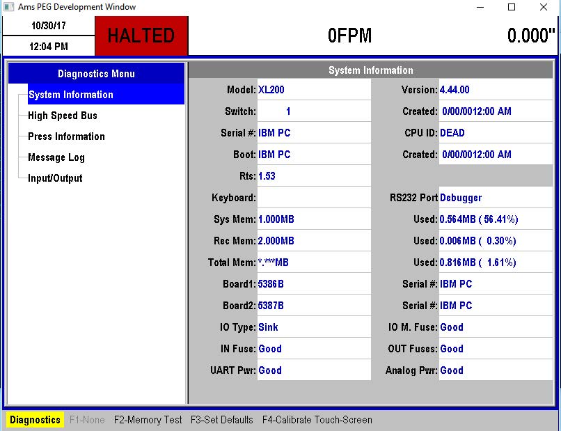
This is a common problem when setting up a scanner for the first time. The below steps will help you to located and identify the problem. In addition, if the controller is in “Debugger” mode when the scanner is plugged in then follow the steps below. You can check for this by touching Diagnostics/System Information and checking the RS232 port. If it says “debugger” the cabling or scanner is NOT configured properly!
- Verify the proper cabling is being used. The bar code scanner CANNOT be directly plugged into the XL200 series controller. A NULL Modem serial cable must be used to interface between the controller and the scanner. If you cannot locate a NULL modem cable, contact AMS Controls to purchase the “Console Mounting Kit” for your scanner.
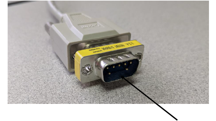
- If you are using a Zebra LI3608 or Sick brand of scanner, you will need to make sure “pin 7 and pin 8” are not connected. This connection can be removed in several places, however, the easiest place would be on the serial cable or the gender changer. See the pic below:
- Verify the Scanner and the XL200 Controller share the same “Ground”. This can be verified by using a multi-meter.
- Go through the scanner settings again! Follow the instructions closely. If you still have questions, contact AMS Controls Support.
