


Punch Programming on the XL200
“It can’t be that easy!”
We often hear these words after describing how to program punch patterns on the XL200 series controllers. This is especially true for customers who are used to spending hours calculating punch progressions by hand. This feature has been part of the XL series for nearly two decades and as a result, many of us at AMS Controls tend to take it for granted. We hope that this will give you an understanding of how our punching system works.
One of the great things about roll forming is the ability to add in-line punching to the operation. In most cases, manufacturers are able to eliminate all secondary operations so that the parts produced on the roll former are ready for use. We have seen many cases where the elimination of secondary operations led to tremendous improvements in throughput and profitability.
Benefits
The following are examples of the most common benefits of the XL200 series punching system:
- Simple programming directly from part drawings.
- Parametric approach allows one punch pattern to work for any part length.
- Seamlessly change part lengths and punch patterns on-the-fly, with no need to stop or create scrap between parts.
- On-the-fly target calculations allows for changes to schedule, automatic handling of coil changes, remaking of parts, etc.
- No cumulative errors.
Basic concept
With many controllers on the market, it is necessary for the customer to calculate the “punch progression”. The punch progression is the series of moves of the material and the activation of punches at the correct time to create the desired pattern. This can be time-consuming and math intensive since the relative distances between the punch tools must be accounted for in the calculations. With the XL series punch programming system, you simply tell the controller where on the part you want each tool to hit and the controller handles all of the calculations automatically and on-the-fly. Of course, it is also necessary to tell the controller the relative distances between the punch tools, but this is only done when configuring the controller for the first time.
Punch References
Punch locations can be referenced along the length of the part (X-axis) or across the width of the part (Y-axis) on machine that have movable punch tools. The following describes each of the ways punches can be referenced:
X-Axis
- Leading edge – The dimension from the leading edge (first edge to exit the machine) to the punch.
- Trailing edge – Distance from the trailing edge (last edge to exit the machine) to the punch.
- Center leading – Distance from the center of the part back towards the leading edge.
- Center trailing – Distance from the center of the part towards the trailing edge.
- Even spacing – This reference creates a series of holes that are evenly spaced. The series starts with a leading edge-referenced hole and continues to the trailing edge of the part or until the spacing limit is hit. Extra punches are added or removed depending on the part length.
- Spacing limit – This limits even spaced punches from getting within the specified distance of the trailing edge. It is used in cases where it is not desirable to have a hole too close to the end of the part.
Y-Axis
In a similar fashion, punches can be located anywhere across the width of the part relative to either edge or the centerline of the part: +Edge, +Center, -Center, -Edge.
Example
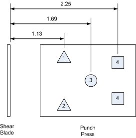
Here’s an example of how to program a simple part using all of the X-axis references. This diagram shows the layout of the punch tools and shear blade:
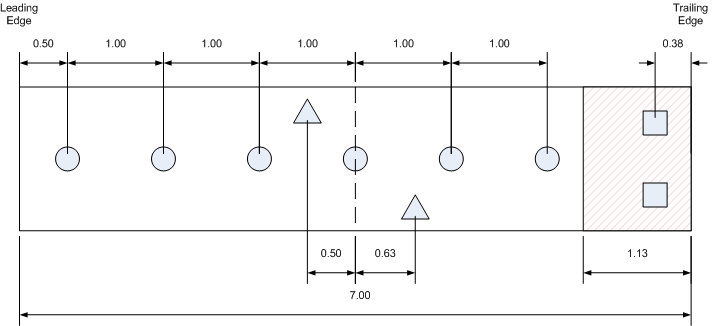
Here is the desired part:
To program this part on the XL200, you would define the punch pattern as follows:
Pattern 1
To make 50 of these parts, you would program a line item as follows:

For this to work, the punch tools must be correctly defined in the XL200 controller:
Some controllers only allow punches to be referenced relative to the leading edge of the part. While this can work fine for very simple cases, it means that a new punch pattern has to be created for every different part length. Since the XL200 can also reference punches from the trailing edge and the centerline, it is very easy to create a punch pattern that can be reused for all part lengths. The even spacing reference makes it a simple matter to handle parts with a series of holes.
Metal wall studs are a common example of this feature. These parts typically have holes spaced every 24 inches (or 600 mm) along their length. Even though they are sold in a wide range of lengths, with the XL200 you can define a simple pattern that works for all lengths:
Part Options
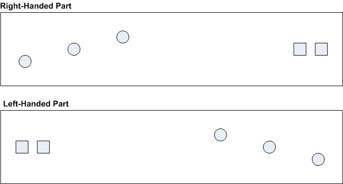
Many parts need to be produced in pairs with both a right and left hand part. A common example of this are track pieces for a residential garage door. Both sides receive the same punch pattern, but the pattern is reversed for one side as it is produced on the roll former. The XL200 part option feature makes it easy to program these types of parts. When a punch pattern is specified as part of a line item, you can select which orientation to use. The following are the available options:
- Right – This is the normal orientation (as programmed in the punch pattern).
- Left – This is the reversed orientation (the leading and trailing references are flipped).
- Alternating – With this option, the XL200 will produce both right and left handed parts alternating back and forth between parts (R, L, R, L, R, L…).
- Mirror – This rarely used option takes all punches between the leading edge and center and “mirrors” the punches to the other side of the part.
We hope this has helped you further understand the XL200 punch patterns function. If you have more questions, please contact Technical Support.
