


Open Loop Flying Boosted Press
Note: Setting up an Open Loop Flying Boosted Press is one of the most challenging setups to do. Boost cylinders are usually operated by air (Pneumatic) and are not the most repeatable devices. The boost adds an added level of inconsistency that can be more of an “Art” to setup.
Boosted Die systems usually have a pneumatic or hydraulic shear down cylinder with an pneumatic operated boost cylinder that is designed to “kick” the die out before the cut is made so that the material is not required to carry the weight of the die when it fires. Firing a press on material that does not stop for the operation can cause material damage due to the weight of the die. The boost helps eliminate that.
Setting up a Boosted Die requires that certain steps be done in order. Skipping a step can lead you down a path which you can “chase your tail”. Below I describe the proper way to setup a boosted system.
Before we get started it is important to know the parameters we will be adjusting. There are 6 main parameters that we will concern ourselves with. They are as follows:
- Shear Dwell – amount of time the AMS Output remains ON to fire the shear.
- Shear Boost Dwell – amount of time the AMS Output remains ON to fire the shear boost.
- Shear Reaction – amount of time before the shear target the shear is fired. This is to account for the mechanical and electrical delay caused by devices. Click here for a full write-up.
- Shear Boost Reaction – amount of time before the shear target the shear boost is fired.
- Die Boost Compensation – used to account for the distance the die travels before engaging the part. Adjusts the first piece after a manual shear to account for this distance.
- Correction Factor – Used to adjust part lengths to nominal.
The following setups must be done in this order. This is very important:
- Set the Shear Dwell. It is important that this parameter be set to the shortest possible time! The less time the shear is engaged in the material the better. The longer the shear stays down after the cut, the longer the die boost must keep the die at the same speed which increases the possibility of a jam-up. Setup your machine with the thickest material and set the shear dwell time just long enough to cut the part. Use the manual shear button to test.
- Set Preliminary Parameters. Set the following parameters to the values below so they don’t affect upcoming steps:
- Shear Boost Dwell = 0
- Shear Reaction = 0
- Shear Boost reaction = 0
- Correction = 100%
- Die Boost Compensation = 0
- Disable the Boost. To properly configure an accurate shear reaction time, we must try and run the machine without a boost. This may cause the part to be damaged in the process, however, we are looking for a part that can be measured. These parts will be scrap so if we can run them, the damage should be ignored. Also, you may need to slow the machine down to perform this test. That is OK. Disable the boost by removing the wire for the boost output. It is important that the boost cylinder has air pressure so the die will return home and stay home as it needs to start from the same position each time.
- Set the Correction. Run a 10-part sample. The longer the better. Throw the first two parts out and record the length of the remaining 8 parts. Assuming these are within tolerance, calculate the average length and perform a “Trim Correction” in the controller using this value as the measured length. Run another 5-part sample, again throw out the first two pieces, and verify the part lengths match the programmed length.
Note: If the 8 parts we are using to calibrate with are not within tolerance, other issues exist. See the section called “Additional Items to Check” later in this document for information.
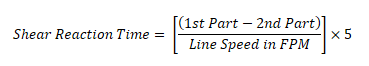
- Set the Shear Reaction Time. Run another 5-part sample and use the formula below to calculate the reaction time of the shear. Note: the formula uses line speed. Enter the calculated number in the controller. Line speed can be read from the controller screen. If we had not set the correction factor in step 4 properly this number would be inaccurate. Therefore, the order of operation is important!
- Re-enable the boost. Re-attach the boost output wire.
- Set an initial Boost Dwell. For the boost output to work at all, you must first set a Shear Boost Dwell time for testing. I would use at least the same amount of time as the Shear Dwell parameter. We will come back and set this parameter accurately in step 9.
- Set the Shear Boost Reaction. Run some more production and visually inspect the part for damage to the leading end of the part. You are looking for the part to be kinked or bent downward caused by the die jamming into the end of the part as it is fired and not travelling as fast as the material. Increase the Shear Boost Reaction by small increments until this goes away. You want this shear boost reaction to be as SMALL as possible, remember the boost can be very inconsistent and should be on for as little time as possible, just long enough to get the die started. Start by setting this number to half the Shear Reaction Time and increase it slowly until the dinging is gone. If you are noticing the part get pulled upward, that is a different issue and is dealt with in step 9.
- Set the Boost Dwell. The boost dwell will be used to get the die clear of the part before returning home. If the die boost time runs out, and the die is not clear of the material, it will grab and pull up one corner or the entire end of the part. Increase this parameter until that issue goes away. Increasing this parameter will not have any effect on the overall length of the part, however, it is best to keep this as short as possible so the die can return home in plenty of time for the next part. It is important that the die can return home and settle so it can start from the same spot every time!
- Set the Die Boost Compensation. Run another 5-part sample. If all the above was successful, your first piece should be SHORT or good, and the remaining pieces will be in tolerance. If you do not have this scenario, repeat the above steps. Measure the amount the first piece is short and enter that value in the parameter.
- Verify the setup. Run another 5-part sample and verify that parts 1-5 are all within tolerance.
Additional Items to Check:
If the above did not work out as written and you are experiencing problems with any part of the process you should check the following:
- Encoder tracking – See Encoder Tracking for detailed information
- Make 100% sure the die is returning to the same hard stop after each stroke. If the die returns to a different home position each time your parts will not be accurate.
- Check the Air or Hydraulic Pressure. For an open loop flying die, it is extremely important that the pressure to the down stroke and boost cylinder be CONSISTENT. Having the pressure fluctuate will cause the press or boost to fire a different way each time. We as technicians have no way of knowing the exact pressure these need, but we can verify the pressure is consistent.
