Open Loop Stopping / Feed-to-Stop
Open Loop Stopping Key Features
- Low Cost
- Low Cycle Rates / Lower Average Line Speeds
- Moderate Accuracy
- Sensitive to Timing / Tracking Variations
- Press Variations Do Not Affect Length
Open loop stopping (also known as feed-to-stop or start/stop) machines are low cost roll forming solutions that have lower throughput rates, because as the name implies, the material must stop for press operations. The benefit of the stopping alternative is higher accuracy. Since the length control system doesn’t have to hit a moving target, press consistency doesn’t affect length. Instead, it is the ability of the material to stop consistently that dictates length repeatability.
Line speeds in stopping applications can vary greatly. Longer parts can be run at higher speeds to increase throughput, but shorter parts must run slower. Some systems have a 2-speed operation so the material is always driven at a constant “slow” speed some distance just prior to the press operation. This ensures the material is always coming to a stop (decelerating) from the same speed, regardless of how fast longer parts are run. Press speed also impacts throughput, because the material must stand still while the press completes its cycle.
Tolerance in open loop stopping applications is often ± 0.060” (1.5 mm) or better. As long as the material is stopped consistently, or if the length control system has the ability to make small corrections prior to cycling the press, length accuracy can be very tightly controlled.
The open loop stopping machine type is commonly used for metal building components (wall and roof panels) and low output light gauge steel framing (stud and track). The application doesn’t lend itself to mass producing large quantities quickly, but this machine type does offer high quality parts on a low cost machine for smaller operations, do-it-yourself builders, and users who service local areas.
The following video (courtesy of Formia) shows an example of a two-speed open loop stopping control. The roll former speed on this machine can be as high as 80 m/m (260 fpm) and the cutting accuracy is +/- 1 mm or better.
Stopping Reaction
When a length control system attempts to stop material for a punch or shear target, the material must decelerate to a stop before the press can be fired. The time required to bring the material to a stop from run speed is the machine’s Stopping Reaction Time. Figure 4-1 describes Stopping Reaction Time with a state diagram.
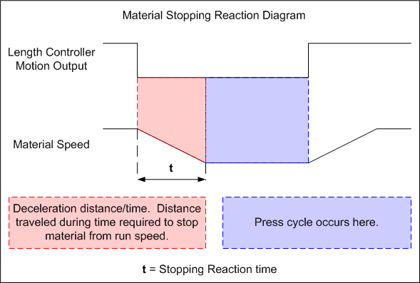
Figure 4-1
When the length controller turns off its motion output, the material decelerates to a stop. If the system waits until the target length is directly beneath the press tool, the press will miss the target. The material will have traveled (coasted) beyond the press tool by the time it stops, as in Figure 4-2.
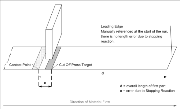
Figure 4-2
Stopping Reaction time can cause the first part after a manual reference to be long or short, and will tend to produce varying lengths due to timing variances in the motor or linkage that drives the material. Timing variances could be the result of varying amounts of material loading the machinery, inconsistent action of valves and solenoids, mechanical backlash in drive systems, or speed changes. Hydraulically driven machines can experience timing variances in cold weather as they tend to be sensitive to temperature.
If the control system can compensate for machinery timing variances, most of the length error can be eliminated. On an open loop stopping machine, the worse the variance, the harder the control system must work to correct lengths. There is a trade-off between throughput and accuracy in the form of longer stops as the system tries to force press targets into tolerance.
Stopping Reaction Key Points
Uncompensated Systems
- Produces a Long Part on Startup
- Sensitive to Speed Changes
- Sensitive to Environmental Changes
- Sensitive to Material Changes
Compensated Systems
- Part Lengths More Accurate from First to Last
- Compensates for Shifts in Machine Timing
- Lower Throughput When Compensating for Machine Timing Changes
- Parameters Must be Set Properly
The XL200 Series and Stopping Reaction
The XL200 controller supports the open loop stopping application with an array of features. On-board functionality, such as 2-speed stopping capability, automatic Stopping Reaction compensation, a Bump Into Tolerance feature, and hydraulic purge allow users to achieve very accurate and consistent lengths. This section also covers Deceleration Factor due to its association with the Minimum Slow Distance parameter and 2-speed stopping.
2-Speed Stopping
One of the key factors in achieving a consistent Stopping Reaction is to ensure the material is moving at the same speed during each material move before coming to a stop. In a single speed system, the speed at which the material runs is based on part length. As lengths change, the machine can’t always get to the same speed with each move. Figure 4-3 shows an example of the motion profile of a machine that runs in single-speed mode.
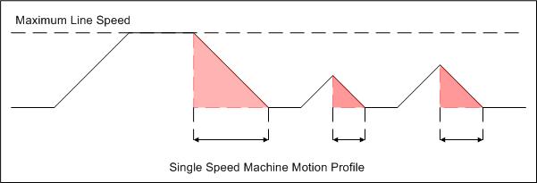
Figure 4-3
The red areas in figure 4-3 represent the decelerations for each material move. From left to right, a long part is run followed by a very short part, which is followed by an intermediate length. Since the machine doesn’t always have time to reach full speed before it must stop for the next press operation, the material isn’t always traveling at the same rate when the line halts. The amount of time required to stop the machine changes with each move. Since time and distance are proportional to each other, the distance required to stop the material must also change.
By shifting the material into a pre-set “slow” speed before each stop, the XL200 series controller ensures the material is always traveling at the same speed from stop to stop. This is done by setting a Minimum Slow Distance. When press targets that are closer to each other than the programmed Minimum Slow Distance occur, the controller starts the machine in slow speed, to ensure an accurate stop. An example of a machine using 2-speed operation can be seen in Figure 4-4.
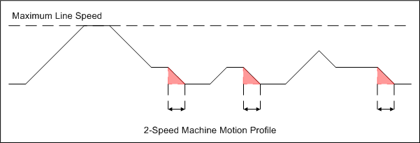
Figure 4-4
It is apparent from Figure 4-4, that when a machine stops from a pre-set slow speed, the stopping action tends to be very consistent. This figure demonstrates the XL200’s ability to always shift the material to the same speed before stopping for a press operation. In the case of a short move, such as the second move in the figure, the controller starts the material at slow speed because it calculates the next press target is within the Minimum Slow Distance parameter.
2-Speed Stopping Key Points
- Consistent Lengths Come from Consistent Stopping Action
- Consistent Stopping Action is Achieved by Reaching Consistent Speed
Deceleration Factor
One of the most misunderstood features of the XL200 series controller is Deceleration Factor. The XL200 does not have direct control of how quickly the machine decelerates. Deceleration is a function of how the machine is driven, the sizing of the motor and what drives it – inverter, hydraulics, or reversing contactors. The amount of material and its hardness also play a roll in deceleration.
The XL200 can only monitor deceleration and minimize its impact on throughput. Since throughput is affected by how long the material must remain at slow speed, this feature is available to shorten the time the machine runs at the slower rate by accounting for how long it takes the material to decelerate. The controller will shift the machine into slow earlier, so it decelerates and reaches slow speed at the Minimum Slow Distance.
It’s important for the material to run at slow speed for some period of time. For consistent stopping times to occur, a consistent speed must be reached.
In Figure 4-4, the motion profile of the machine was represented as a perfect trapezoid. In reality, each time the machine slows from fast to slow, the material will require a small time period to settle to the exact slow speed desired before stopping. This time is usually small, but for accurate stops, it is important that the machine and material be given enough time to settle into slow speed. Figure 4-5 provides a more realistic example of what happens when a machine changes speed.
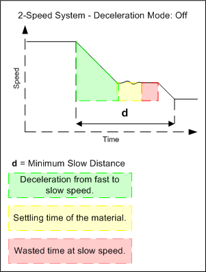
Figure 4-5
As the descending line in Figure 4-5 demonstrates, the material speed is not constant for a short time after the machine shifts speeds. Too much time at slow speed is wasted throughput. If 0.1 s of time is removed from a process that yields 1 part per minute, then in an hour the same machine could produce 6 more parts.
With Deceleration Mode set to Automatic, the XL200 series controller calculates the deceleration ramp when the machine shifts from fast to slow. On successive speed changes, the controller shifts the machine into slow speed earlier, so the material is at slow speed by the time the material reaches the Minimum Slow Distance. Figure 4-6 continues the example after setting Deceleration Mode to Automatic, but without adjusting any other parameters.
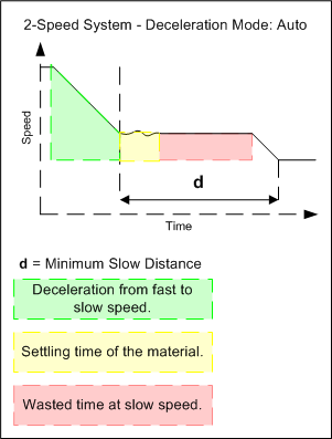
Figure 4-6
In Figure 4-6, the XL200 controller can shift the machine into slow speed so that the material is at slow speed at the programmed distance. Now, maintenance or engineering can adjust the Minimum Slow Distance parameter until the machine stops consistently, but doesn’t run for too long at slow speed (See Figure 4-7).
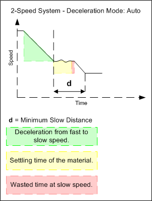
Figure 4-7
Deceleration Compensation Key Points
- Deceleration Compensation Reduces Minimum Slow Distance
- Shorter Minimum Slow Distance Translates to Greater Throughput
Automatic Stopping Reaction Compensation
By default, each time the machine stops for a press operation in the Run mode, the XL200 series controller calculates how much time elapsed from the point when its motion outputs turned off till the material speed reached 0 fpm (0 mpm). It updates this value in a parameter called Stopping Reaction Time.
On the next stop, the controller uses the time from the last stop to help minimize variance. In this way, the XL200 series controller compensates for some machine time variances. If the machine has large swings in Stopping Reaction Time, then the material will probably fall out of tolerance. When this happens, the controller will warn the user and exit the Run mode. The Stopping Reaction Time parameter is not updated when an out of tolerance stop is made, because the assumption is that the time is not a good value.
In many cases, a large shift in Stopping Reaction time indicates there is something wrong with the material or equipment. It could be the material is dragging on a guide or becoming jammed in the machine. The machine could have a problem with a solenoid that is failing, or a valve that has become “sticky”. Wear and tear on the chains, gearing or couplers of the machine will create backlash causing the material to actually back up a bit after it stops. This is common with chain driven machinery, because chains will slacken over time.
Sometimes a machine is built with these issues inherent in the machine design. Because the application is very low cost, the user of the equipment is expected to accept the nature of the machine and the process. Constant maintenance is required to keep the machine operating at peak efficiency. Otherwise, the user must rely on control features such as the XL200’s Bump Into Tolerance functionality to produce accurate and consistent parts on a machine that would otherwise be incapable of doing so.
Bump Into Tolerance
The XL200 Series controller can make small adjustments to the material position before firing a press in the automatic mode. AMS Controls calls this “bumping into tolerance”.
The Bump Into Tolerance feature uses three parameters to force the machine to produce good parts:
- Tolerance – The Tolerance parameter is a standard parameter that is always used in the open loop stopping application. When the user sets this value, he tells the XL200 Series controller that lengths outside of this range (+/- the value entered) are unacceptable. If the machine stops for a press operation in the Run mode, and the material stops outside the programmed range, the XL200 will exit the Run mode and display the “Out of tolerance” error to the operator.
- Bump Tolerance – Bump Tolerance should be programmed at a value larger than the Tolerance parameter. If the machine stops for a press operation in the Run mode, and the material is outside of the programmed Tolerance, but still within the programmed Bump Tolerance range, the controller will not display “Out of tolerance”. Instead, the XL200 will attempt to force the material into Tolerance by turning on its motion outputs for a time equal to the programmed Bump Time.
- If the material stops outside of the programmed Bump Tolerance, the XL200 will exit the Run mode and display the “Out of tolerance” error to the operator.
- Bump Time – The Bump Time is the amount of time required to get the material into motion. Generally, this should be a very small amount of time, as the longer the time, the larger the material move. This time will be different for every machine and is based on the mechanics of the machinery.
Figure 4-8 graphically represents the concept of Bump Tolerance. The green band of acceptable tolerance represents the value programmed into the Tolerance parameter. The red bands on either side represent the area described by the Bump Tolerance.
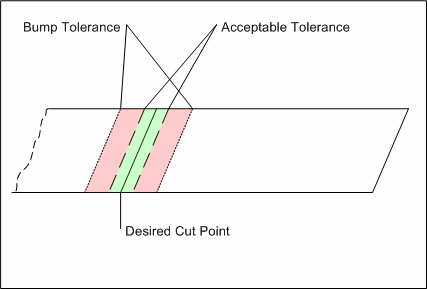
Figure 4-8
The XL200 Series controller will use its outputs to cause the machine to bump the material forward if the material stops short (Figure 4-9) or reverse if the material stops long (Figure 4-10), respectively.
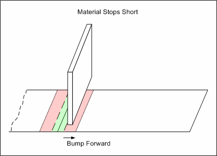
Figure 4-9
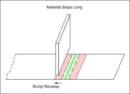
Figure 4-10
Bump Into Tolerance solves a lot of problems related to the machine, but the trade-off is a reduction in throughput. If the machine can not consistently stop the material, the XL200 Series controller must work harder to nudge the material into Tolerance. The tighter the Tolerance and the less consistent the machine, the longer it will take to produce a good part.
Situations where the machine spends a lot of time “bumping” could indicate the Bump Time is set too long, or the machine has become mechanically less consistent over time.
Hydraulic Purge
Hydraulic systems are often used in the open loop stopping application for machine movement, because hydraulic fluid is generally considered to be incompressible, for practical roll forming purposes. This provides a very stable means of control.
When valves open to allow fluid to flow, the machine reaches Run speed very quickly. Consequentially, the stopping action on a hydraulically driven machine tends to be very consistent. As long as high-quality valves are used, and those valves are driven directly by the controller’s outputs, timing variances should be kept to a minimum.
A potential pitfall of using hydraulics is the viscosity of hydraulic fluid, the resistance of the fluid to flow, changes based on temperature. Most of the time this is not a problem, but when a machine sits idle for a long period of time (overnight) and the temperature in the building is cold, the machine’s timing is going to be affected by the cold hydraulic fluid.
One solution to this problem is to add a heater element to the reservoir. For systems that don’t incorporate a heater element, the XL200 Series controller provides a Hydraulic Purge function. Hydraulic Purge is a function found under the Diagnostic menu of the XL200.
The operator can choose to cycle the shear press, punch presses, or all presses using Hydraulic Purge. This feature causes the controller to cycle the selected presses over and over. This forces hydraulic fluid to flow through the system, warming the fluid and ensuring it’s cycled through the cylinders and hoses. If this is done at the beginning of the shift for a period of time, then the machine should be “warmed up” by the time production begins.
Summary
Open loop stopping systems provide a low cost, moderate accuracy solution for roll forming applications. Throughput is relatively low, especially when tolerance requirements are tight.
Part length repeatability is not affected by press consistency, but relies instead upon the machine’s ability to stop consistently. Reliable stopping action comes from hitting uniform speeds, and avoiding mechanical backlash.
The XL200 Series controller has several on-board features that compensate for timing variances that come from mechanical inconsistency. The greater the variance, and the tighter the tolerance requirement, the more throughput can be affected.