Open Loop Flying Die
The open loop flying die machine is a low cost solution that offers high throughput. Line speeds can exceed 500 fpm (150 mpm). Accuracy on this type of machine is usually around ± 0.06” (1.5 mm). Tighter accuracies are possible with this application, but they require precision in the setup of the material encoder, and robust maintenance of the equipment to keep it functioning optimally.
Open Loop Flying Die Key Features
- High Cycle Rates / High Line Speeds (up to 4 hits per second)
- Low Cost
- Moderate Accuracy
- Higher Accuracies Require Regular Maintenance
- Sensitive to Timing / Tracking Variations
One of the most common uses of this application is in steel stud production. Stud lines typically use closed loop flying dies for their cut off operations, but the punching of the knockouts (holes in the stud used to run conduit and plumbing) are generally open loop flying die with boosts. Knockouts on a steel stud don’t require tight tolerances, but punch presses must fire at short intervals – as close as 18” (460 mm). On machines that produce studs at speeds in excess of 400 fpm (120 mpm), open loop flying die is the perfect application for knockout punches.
There are generally two major variations of the open loop flying die application; boosted and unboosted dies. A boost is a hydraulic or pneumatic cylinder used to push or pull the die up to material speed. Some systems even use a proportional valve to more accurately match material speed with the die. Generally, boost cylinders are required for higher line speeds.
Press Reaction
Whenever a length control system signals a press to begin its operation, the time between when the control system turns on its output, and when the press tooling contacts the material is called Press Reaction Time (see Figure 3.1).
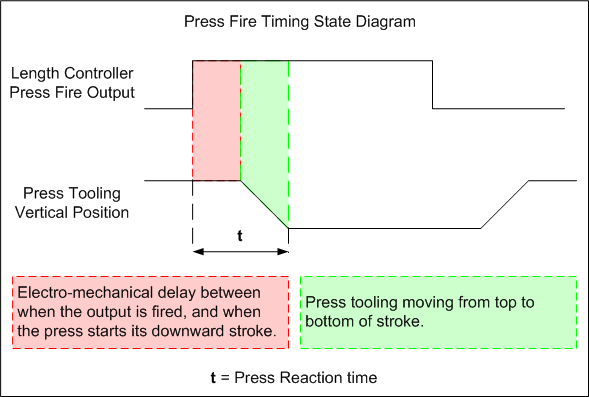
Figure 3.1
If the first part produced by a machine is long, it’s usually because of Press Reaction time (Figure 3-2). The industry commonly accepts this wasted material, because many control systems lack timing parameters to compensate for the error. Roll forming operations that use in-line punching struggle with the problem of uncompensated press reaction by virtue of having multiple reference points to keep aligned on a finished part.
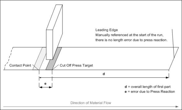
Figure 3-2
Because time, distance and speed are directly proportional on a roll former, lengths on an open loop flying die must grow when the line speeds up, and shorten as the roll former slows. After a couple of parts, the lengths will appear to stabilize. Unfortunately, on an open loop flying punch, the entire pattern can shift in relationship to the leading or trailing edge.
If the system can not compensate for Press Reaction, the error must be reconciled by changing the distance values for the presses. Length control systems that are capable of automatically compensating for Press Reaction can reduce or eliminate length shifts due to speed change for all presses they control. But even compensated length control systems can miss targets when parameters are set to improper values.
Press Reaction Key Points
Uncompensated Systems
- Produce a Long Part on Start Up (after a manual reference)
- Lengths and Punch Patterns Shift During Speed Changes
- Encourages Incorrect Parameter Settings by Operations
Compensated Systems
- Part Lengths Accurate from First to Last
- Part Lengths Do Not “Shift” During Speed Change
- Punch Patterns Do Not “Drift” During Speed Change
- Parameters Must be Properly Set
The XL200 Series and Press Reaction
The XL200 controller has several features to support the operation of open loop lines that cut and punch on-the-fly. Primarily, the XL200 accepts a Press Reaction value for each press it controls.
Assuming a press is operating consistently, its reaction time must still be factored into the firing of the press for length accuracy for all parts. When any length control system tries to hit a moving target with an open loop press, it’s going to miss the target if it waits to fire the press until the target is directly under the tooling.
The XL200 pre-fires presses based on their reaction time and the current speed of the material. If the speed changes, the controller adjusts the distance from target that presses are fired. This eliminates long parts on start up and creates smooth transitions for punch patterns during speed changes.
To gain these benefits, the XL200 must have its parameters properly configured. The Press Reaction Calculation Procedure offers a step-by-step method for calculating Press Reaction time.
Length Variance
In the open loop flying die system, the only feedback for length control comes from the material encoder. The length control system references the encoder to the shear (and all other flying presses on the line) by virtue of the fact that the material should be a straight line between those points. When the roll former pushes material forward in the automatic mode, the length control system counts encoder pulses for distance measurement and fires presses based on that measurement.
For part length consistency and accuracy, encoder tracking is critical, but so is press consistency. Fast acting and repeatable valves are important for producing consistent punch locations and part lengths. The faster the line runs, the more important the timing of the press firing becomes.
The only way to verify Press Reaction time is to measure it. If the timing is consistent, this is a simple matter, but if a variance is suspected, the measurement process is more involved. Example 1 describes a situation where variance in Press Reaction time is a problem:
Example 1:
A roll former produces parts at a rate of 100 fpm (30 mpm) and the acceptable tolerance range on finished parts is ± 0.060” (1.5 mm). Part tolerance has been varying by 0.6” (15 mm) for the last few days.
After examining the encoder assembly and performing some basic tests on the control system, the determination is made that these areas are functioning as expected. Suspecting a variance in press timing, maintenance checks press consistency using an oscilloscope.
Maintenance finds that the press has a reaction time variance of 0.03 s. “30 milliseconds” doesn’t sound like much time, but speed multiplied by time equals distance:
s · t = d
s = speed
t = time
d = distance
s = 100 fpm (30 mpm) or 20 ips (500 mmps)
t = 0.03 s
20 ips (500 mmps) · 0.03 s = 0.6” (15 mm)
Simply due to the inconsistency of the press, the part lengths on this machine vary by more than 0.5” (12.7 mm).
Speed fluctuations can cause length problems that look like timing variances. Solenoid driver (“slammer”) boards, such as the AMS Controls Slammer Module, can help mitigate the effects of such speed changes. The Slammer accepts the 24 VDC signal from the length controller and changes it into a 45, 60, 75, or 90 VDC signal.
DC solenoids are more responsive than AC solenoids, due to the nature of how the coil builds its electrical field. AC solenoids can often be fired using DC current, making them more consistent. Even DC solenoids can be made faster acting and more consistent by using a slammer board. The Slammer fires its output at the higher voltage only for the first 0.03 seconds, to get the solenoid to shift quickly, then the Slammer drops its voltage to a 24 VDC holding signal for the remainder of the press cycle time to protect the life of the solenoid coil.
Boosted Dies
Boost cylinders are most often used in open loop flying die applications to keep the material and tooling from being damaged by the press operation. If the die is heavy, or the press operation generates too much force, the material might not be strong enough to support the die and retain its form. Using the material to drag the die up to speed can result in excessive wear on the press tooling. In these cases, the die will need a boost cylinder.
High speed lines usually require boost cylinders for the dies. If these lines run at lower speeds, though, the boost might not be necessary. Boosts sometimes add variance to the overall length of the system. Some boosts are driven directly by shop air, and don’t have their own accumulators. As leaks occur in the system, or as other equipment draws down the pressure, the boost doesn’t consistently push the die at the same speed and with the same timing characteristics from stroke to stroke.
The boost cylinder can also benefit from a slammer module, just like the press cylinder. The action of the solenoid can be made faster and more consistent, thus eliminating timing and speed variances inherent in the system.
The XL200 Series and Boosted Dies
Boosted dies are well supported in the XL200 Series controller.
Boost Enable Velocity
In order to help compensate for a “sloppy” boost at lower speeds, the XL200 allows the user to define a speed under which the boost is not used when firing the press. When running production under this velocity, the boost is not required to support the weight of the die. Above this speed, the material is moving too fast to avoid being damaged if the tooling enters the material unboosted.
Velocity at Max Analog Voltage
Sometimes, the boost is hydraulically driven. Often, hydraulic boosts are controlled with a proportional valve. This gives the user the ability to more accurately control the speed of the die with relation to the speed of the material, providing a more accurate and cleaner press operation.
The XL200 has an analog output (± 10 VDC) that can be directly scaled to line speed. The parameter Velocity at Max Analog Voltage assigns the upper limit of scaling for the analog output. For instance, setting Velocity at Max Analog Voltage to 200 fpm (60 mpm) means the controller’s analog output will be linearly scaled from 0 – 10 Volts from 0 – 200 fpm (60 mpm).
Die Boost Compensation
Since the boost should not fire unless the material is in motion, the XL200 only fires the boost output when in the Run mode. In order to compensate for the distance not traveled by the die when the press is fired during standstill, there is a Die Boost Compensation distance parameter. When the operator references the cutoff press during standstill, the XL200 will adjust the first part by the distance the cutoff die will travel when the boost operates in the Run mode.
Boost Dwell and Boost Reaction
Just as each press fired by the XL200 has a dwell and a reaction time, each boosted press will have dwell and reaction parameters. Press Boost Dwell is the amount of time the controller fires the boost output. Press Boost Reaction is how early it fires the output.
Some machines are designed so the die must be boosted up to material speed before the press is fired. This gives the die time to reach material speed so the die’s weight is not resting on the leading edge of the material. On other machines, the boost is so powerful the press should be fired before the boost. On yet other machines, the press and boost should be fired simultaneously.
For greatest flexibility, starting with XL200 v2.10 software, AMS Controls allows the user to program the boost dwell and boost reaction parameters with as much independence as possible. The initial boost output is based on the original press fire target, regardless of any other settings.
The Shear Dwell Up and Shear Dwell Down parameter functions identically in both the old and new software versions. The time entered must still be found by trial-and-error by performing standing cuts on the thickest material that will be run through the machine.
With only the Shear Dwell set, the corresponding boost output will not turn on. In Figure 3-3, a shear/boost combination is programmed with Shear Dwell time. Only the shear will turn on for 0.1 s of time.
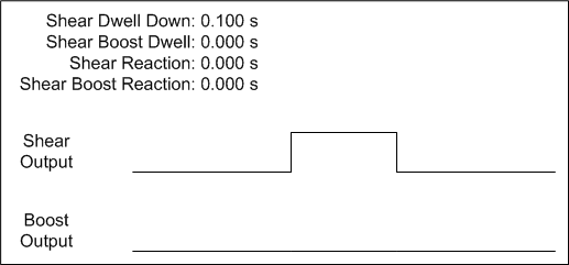
Figure 3-3
In any mode of operation, the system must account for the reaction time of the press in order to make accurate parts from start to finish and through all speed ranges. While establishing the Shear Reaction time, the boost cylinder should be disabled so that it does not impact the operation of the shear die. This can typically be accomplished by removing the solenoid of the valve that controls the boost. The test for Shear Reaction can then be performed at a speed slow enough that the material will support the weight of the die without the boost.
In some cases, it is not possible to fire the shear without using the boost. In this case, the parameters will have to be “dialed in” through trial-and-error.
Once the shear press reaction time is determined, it is entered into its corresponding parameter. This only affects the shear output in Figure 3-4. The boost output “on” state will be based on the original target coincidence point (where the shear would have originally turned on).
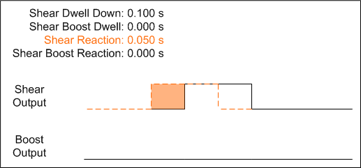
Figure 3-4
After entering the parameters above, the boost is reconnected to the die and some sample parts are run. Often at this point, it might be observed that the shear blade is dragging, or “hanging up” on the leading edge of the material. To solve this problem, some amount of Shear Boost Dwell is added in Figure 3-5 to continue pushing the die forward as the shear blade retracts out of the material.
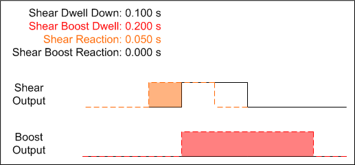
Figure 3-5
At this point, the shear is fired 0.05 s before the boost turns on. When the boost is fired, it stays on longer than the shear output, allowing the shear to retract with no back pressure on the material. However, at higher speeds, the user might notice some buckling on the leading edge of the next piece. This is an indication that the shear die is not fully up to speed by the time the shear blade contacts the material. To solve this problem, Shear Boost Reaction is added in Figure 3-6 as a way to get the shear die moving earlier, so the die has time to more closely meet line speed by the time the blade contacts material.
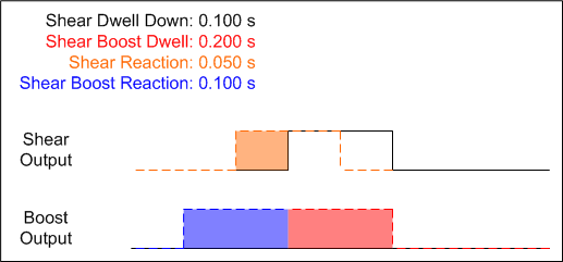
Figure 3-6
After the last parameter change, the boost output fires 0.05 s before the shear output, helping to bring the die up to material speed before the blade contacts the material. Because of the shift in reaction time, it might be necessary to go back and increase the Shear Boost Dwell parameter to force the boost to keep pushing the die as the blade retracts out of the material, if the material starts to hang up on the blade again.
Summary
Open loop flying die applications provide low cost, high speed solutions for roll forming customers. Good accuracy is possible, but requires diligence and maintenance of the system, especially over time.
Repeatability of part lengths relies on good encoder tracking and consistent press timing. Slammer boards are helpful in reducing press reaction times and increasing press solenoid consistency.
Through the use of the Press Reaction parameters in the XL200 series controller, open loop flying die machines can provide good part lengths from first-to-last, and through speed changes. For machines that use boosted dies, the XL200 controller provides a range of support options that allow the user to customize the system to their specific equipment needs.