


Closed Loop Flying Die / Die Accelerator
In the closed loop flying die application, press tooling is accelerated (these are sometimes called “die accelerator” systems) to material speed and matched to the target position on-the-fly. When the press is cycled, the tooling is standing still with respect to the material, so accurate, high-quality press operations can be performed without impacting throughput.
Closed Loop Flying Die Key Points
- High Accuracy
- High Speed
- Not Sensitive to Timing Variations of Equipment
- High Cost
- Very Sensitive to Encoder Tracking Variations
- Requires Higher Expertise for Startup and Troubleshooting
With higher performance comes higher cost. In addition to a length control system, a servo system and mechanical actuation equipment are also required. Closed loop flying die systems also require a level of expertise with servos to get maximum performance from the system. This means servicing equipment can require a higher level of technical aptitude, as well as more specialized testing equipment (oscilloscope, laptop, special cables).
Closed Loop Flying Die Post Cut
One common use of the closed loop flying die application is in high-speed stud and track lines. The cutoff for such a machine will often be a belt-driven servo shear, though this is also a mix-and-match application, since the punching is typically done with an open loop boosted flying die. The cutoffs on these lines are servo controlled for higher speed and accuracy, but the punches are open loop because the tolerances are less critical than overall length.
Decking mills will often use closed loop flying die cutoffs, but not necessarily because they require high accuracy. Throughput is most important on these mills, but the cutoff is too heavy to rely on a boost cylinder to provide good speed matching. Any back-pressure from the cutoff results in a material crash and downtime. On these machines the servo is really there because of its speed-matching capability. That’s why these lines often use a rack & pinion actuation system. These might be less repeatable than other actuation methods, but they are robust enough to handle moving a heavy die at high accelerations. This allows the machine to produce parts that are “good enough” on a shorter press bed than would normally be acceptable.
Actuation Methods
There are several servo actuated equipment types that can be used to move press tooling to match material speed and position. The most common types are listed below.
Types of Servo-actuated Flying Die Systems
- Ballscrew Actuator
- Belt-driven Actuator
- Rack & Pinion Actuator
- Servo Hydraulic Cylinder
- Rotary
- Crank
- Linear Servo Motor
Ballscrew Actuator
Ballscrew actuators do not typically require a gearbox from the motor to the screw, since the screw itself provides its own gearing. This means there are fewer mating points between the output shaft of the servo motor and the load. These tight mechanical couplings in combination with a cold rolled screw offer extremely accurate positioning. Rolled screws are preferred to precision ground as they are more robust. Precision ground screws tend to be more brittle and far less forgiving when material crashes occur.
These types of actuators use a ball-nut, filled with bearings to traverse the length of the screw as it turns. The bearings wear out over time and the entire unit must be serviced. They are also susceptible to shock from die crashes and heavy loads. Quality ballscrew actuators are expensive, and many manufacturers do not stock specific models because of the diverse requirements of the many industries that use them. This translates to long lead times for replacement units, so a spare is advised.
Ballscrews are limited in the speeds they can achieve. Since the screw is spun from one end, and both ends are held in place by bearings, spinning the screw too fast can cause it to deform as its physical form takes on a “jump rope” appearance.
Belt-driven Actuator
Belt-drives are good for high-speed, high-accuracy systems. The mechanics of the belt-pulley system are simple, but for best results, a high quality gearbox and belt should be used. These items drive the cost up, but the result is less mechanical backlash which translates to higher accuracies on finished parts.
An important consideration for belt actuator users is selection of an appropriate belt for the application. Most product selection guides work well for “pick-and-place” applications, but often suggest a belt that is too small for flying dies. Pick-and-place applications aren’t generally as concerned with “ring out” during motion, whereas this is a critical concern in a system that’s trying to match speed and position on-the-fly.
Rack & Pinion Actuator
Rack and pinion systems are good for moving a heavy die at high accelerations. The mechanics of the system are more forgiving of the larger forces and handle presses with higher instantaneous shock (cutting force). These “beefed up” mechanics are costly because the mountings are (usually) large, thick steel plate. The rack and pinion gears themselves are usually large and made from hardened steel.
The plate that holds the rack against the pinion gear requires constant lubrication. Variance problems due to wear of this plate is common. The forces in these systems also tend to take their toll on the keystock used to match the pinion gear to the output shaft of the gearbox. It’s common to see variance problems due to a rounded piece of keystock.
Due to the nature of the rack and pinion assembly, mechanical backlash can be a problem over time. This backlash can translate into length errors.
Servo Hydraulic Cylinder
Servo hydraulic systems are most often seen in the tube & pipe industry. The systems are good for moving a heavy die quickly, and they offer high accelerations. The cylinders can run well with less maintenance since there are fewer moving parts to wear out, so they are known for “taking a beating”.
The downside to servo hydraulics is that they require an understanding of hydraulics and servos to setup and troubleshoot. The technology that drives the servo portion of the system is still mostly analog, so setup of a new or replacement system can be difficult and time consuming. Dead-band/hysteresis and other non-linear effects can sometimes be a problem when high accuracy is required.
Rotary Presses
In other actuation methods, rotary motion is being translated mechanically into linear motion to match the linear motion of the roll formed material. In a rotary system, the servo rotates a drum, matching speed with the material just prior to the tooling entering the material, and staying matched until just after the tooling exits the material.
These systems are good for high speeds, and with proper gearing and control algorithms, can often accomplish more work with less motor. On the other hand, rotary systems are most often limited to light gauge lines. Sharpening of the tooling is more difficult and expensive due to the curved profile of the cutting edges.
Crank Systems
Sometimes called a “rotary crank,” these systems are most like a piston in an engine, or a steam locomotive piston rod. The servo motor spins a crank, and a piston rod is connected to the outside diameter of the crank by a journal. The other end of the piston rod is connected to the die. The servo only needs to spin in one direction for the die to move from fully retracted to fully extended and back again.
Crank systems are comparable to most other systems, except the mechanical linkages are more complex, as is the mathematics to translate the rotary motion to linear travel. The system itself is not linear, so the control algorithms are more complex. Based on the specific mechanical design, the control system might have to compensate for large swings in inertia.
Linear Servo Motor
Linear servos offer extremely high accuracy. The accelerations possible from a linear servo will generally far exceed what’s possible from a rotary servo motor. This increased capability is balanced by cost. They tend to be more expensive than conventional rotary motors, and often require liquid cooling systems for optimum performance.
This technology is not yet very commonly used in roll forming. Due to the nature of cutting metal (slivers, dust, shavings, slag), these systems can be a maintenance problem because it’s difficult to keep contaminants out of the magnets and position feedback portions of the servo.
Linear Motion Profile
Regardless of the specific type of linear actuation system used, the physics of the tooling motion profile is the same. Mathematically, the forward travel motion profile of a closed loop flying die is generally trapezoidal.
For the return stroke of the die that brings the tooling back to home position, the motion profile might be a trapezoid, or a triangular move to minimize travel time and maximize throughput. A triangular motion profile is harder on the mechanics of the system, but this is balanced against increased production rates.
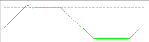
Trapezoidal Motion Profile – Forward and Reverse Direction
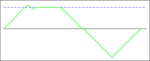
Trapezoidal Forward Profile – Triangular Return
Die Reference Modes
The XL200CL has three different modes that determine how and where the acceleration ramp starts:
- Home – The flying press or die always starts at the home position. The press accelerates until it matches the material speed and the cut or punch press is activated once it gets to the programmed minimum die distance. With this mode, it may be necessary to adjust the min. die position to get optimum accuracy and throughput at different speeds.
- Min. Die – The flying press or die’s home position varies depending on the line speed. The starting position is calculated as the minimum die position minus the distance required to accelerate to the current material speed. An optional settling time parameter can also be used to shift the starting point so that the die is at the minimum distance once the settling time is complete.
- Max. Die – The flying press or die’s home position is automatically adjusted so that the end of the stroke is always at the maximum die position. This is very useful in cases where a range of parts lengths are produced. Long parts are typically run at higher speeds (requiring longer stroke lengths). Short parts need to be run at lower speeds because of the cycle rate of the press. At slower speeds, the starting position of the press is very near the maximum die distance. This means the cut will always occur as close to the end of the slides as possible. This makes the handling of short parts much more reliable.
Tolerance Modes
One of the advantages of a closed-loop flying system is the fact that the controller can wait until the tool is within tolerance before activating the press. With open-loop flying systems, the press is fired in anticipation of the target and there is no chance to make adjustments. The XL200CL has a few different modes that control how the tolerance test is performed and what happens if it is not possible to fire the press within tolerance:
- Stop, No Cut – Once the minimum die position is reached (or after the settling time is over), the controller checks to see if it is in tolerance before turning on the press. If the die gets to the maximum position without being in tolerance, the machine is halted and an error message displayed.
- Cut & Stop – Once the minimum die position or setting time is reached, the press is fired. At the bottom of the press stroke, the tolerance is checked. If the shear or punch operation was out of tolerance, the machine is halted and an error displayed.
The following two modes only apply on the XL200CLT (tube/extrusion) model:
- Warn Only – This works the same as the “Cut & Stop” mode except that the machine is not halted (a warning message is still displayed).
- Warn, No Cut – This is the same as the “Stop, No Cut” except that the machine is not halted. Measures must be taken to ensure that double part lengths (or longer) do not pose a safety risk.
Other XL200CL Features
Advance After Cut – This is typically used on machines with a saw cut. After the down-stroke of the press/saw, the press is moved forward by the specified distance before being brought back up. This prevents the blade from damaging the leading end of the part. To prevent causing damage to the trailing edge of the previous part, it is necessary to have an exit conveyor (or equivalent mechanism) that is running at a faster speed.
Press Reaction Time – In some cases where a very high part rate is needed, it may be necessary to turn on the press early so that no time is wasted once the die is matching speed. A reaction time can be specified which will cause the press to be fired before the press is expected to be in tolerance. While this may improve production rates, care must be taken to ensure tolerance does not suffer. In some cases premature tooling wear or part damage can occur if the press hits before matching speed.
Two Speed Operation – With a flying press, the available stroke length, press dwell, acceleration rates, and other mechanical concerns limit the maximum material speed. With the XL200CL, it is possible to run the roll former at two speeds. The slower speed is the max speed of the accelerator/press mechanics. The machine runs at the faster speed until the cut or punch target gets close. It then shifts to the slow speed for the cut/punch. The XL200CL switches the roll former between the two speeds automatically.
Summary
Closed loop flying systems can produce very accurate parts at high speeds. They are typically immune to external conditions and produce good results regardless of the experience or skill level of the machine operator. They are also more expensive and can take more expertise to initially setup. In spite of the higher cost, more and more roll forming machines are being converted to this technology all the time. There are sound financial justifications for this trend.
