


Roll Forming: The Four Basic Machine Types
AMS Controls’ core business is machine control and production management for roll forming industries. As such, length control is a primary focus, so we wanted to produce a series of articles on issues that can cause length variance– where problems come from, and how to eliminate them. Once we got past encoder issues (which are common across all machine types), we wanted to tackle length control based on machine application – non-stop vs. stopping, servo control vs. non-servo control.
Before launching into a series of articles detailing the different machine types, we realize an introduction to some basic concepts is in order. AMS Controls defines some common terms and jargon that are particular to the types of control systems we provide.
This article covers the four basic machine application types very generally, describing functionality from a high level. A few pros and cons are listed, but each application will be covered in greater detail in subsequent articles.
Lexicon of Roll Forming Terms
The roll forming process is used across a range of industries. As a result, there are a number of different terms used to describe similar equipment and processes.
To simplify explanations and facilitate a common understanding of the process, AMS Controls has created a list of roll forming terms and their meanings:
The Four Basic Machine Application Types
AMS Controls categorizes roll forming machines into four general application types. Anything beyond these four basic machine types is usually just a variation on a theme, or it’s a compilation of a few basic applications rolled into one. Understanding the individual “basic application” allows easy understanding of the more complicated combinations.
There are some specialized machine applications that don’t fully fall into the four basic types, but those are rare exceptions. We’ll cover the more specialized machines in articles specific to those applications.
Machine applications are primarily classified by the presence of a servo system for either material or press tool positioning, and based upon whether the material stops for press operations, or if press operations occur on-the-fly. The four application types are:
Before discussing each application, it’s important to understand the basics of the categories to some degree. It’s also important to understand the reasons behind why the different categories exist.
There are three major factors that influence which type of machine will be used to produce a certain roll formed product – throughput, accuracy, and cost. Floor space is another consideration, but it isn’t as important to all consumers, and is really outside the scope of this article.
When weighing the three factors against each other, usually two factors will win out over the third. If low cost and high accuracy are important concerns, throughput will likely be lower. If high accuracy and high throughput are important, the system will cost more.
Open Loop Stopping
The more accurate of the two open loop length control methods, stopping machines have lower through-put rates than flying applications. These characteristics are balanced against cost, which is lower for open loop systems.
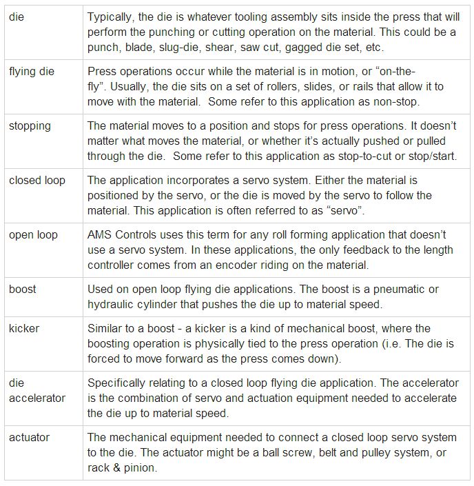
Figure 2-1 shows a cut off press with a fixed-base die. The actuation method of the press is unimportant; it could be hydraulic, pneumatic or mechanical. The important aspect of this press is that the die is fixed in its position and cannot move.
In stopping applications, it is the material that is positioned by the machine. The length control system must start and stop the material so the correct length is past the exit side of the cut off die before the press is fired. The accuracy and repeatability of part lengths is tied to the machine’s ability to bring the material to a stop at the same rate from move to move.
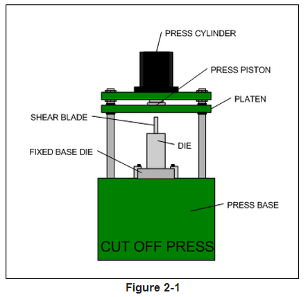
On post-cut machines, the material is formed before it is cut to length. Figure 2-2 illustrates a post-cut stopping machine.
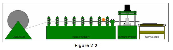
Figure 2-3 shows a pre-cut stopping roll forming process. The material is fed by a set of rolls controlled by an AC motor, cut to length, and then rides along a conveyor belt to the roll former.
While pre-cut lines are generally slower than their post cut cousins, the equipment expenses are lower. The roll former runs at a constant rate, which saves wear and tear, and these systems generally have simpler cut off dies.
Open Loop Flying Die
In flying die applications, throughput is the key concern. These systems are capable of high speeds, and accuracy could be as good as ± 0.032” (0.8128 mm). Like the open loop feed-to-stop, these systems have a very low cost compared to closed loop systems.
The operation of most open loop flying die machines is simple. Material runs at a consistent speed most of the time. Line speed might be adjusted by the operator, but speed is usually only changed when part lengths change; shorter parts running at slower speed, longer parts at higher speeds.
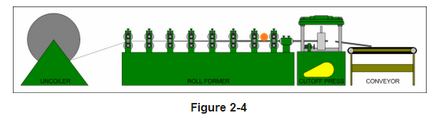
When the correct length has been reached, the control system fires the press. The cut off blade enters the material, and the material pushes the die forward while the cutting action is taking place. When the cut is complete, the press retracts the blade out of the material, and the die is returned to its originating (home) position. The return is usually accomplished with springs or an air cylinder. Figure 2-4 shows a standard open loop flying die process.
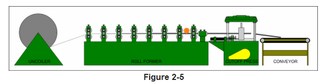
In some cases, the finished shape (profile) of the material is not strong enough to support the weight of the die at the speed the machine is running. To keep the material from being damaged, a boost cylinder can be mounted to the die, as in Figure 2-5. This cylinder might be hydraulic or pneumatic, but its function is to push the die up to material speed as the press is being fired. This helps to relieve the stress of the weight of the die on the material.
Closed Loop Feed-to-Stop
Closed loop usually means a high degree of accuracy. Feed-to-stop systems have lower throughput, but the tolerance for punching and cutting operations can be as good as 0.003” (0.0762 mm) or better. Closed loop servo systems do tend to cost more than open loop systems.
In Figure 2-6, a closed loop servo drives a set of feed rolls on the entry side of a hydraulic press. In this application, it’s typical to use only the servo feedback as the measurement system.
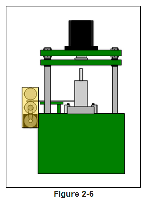
In some situations, slip is a known factor between the feed rolls and the material. When slip is a problem, a material encoder can be added to the setup. Since the encoder wheel is not driven, its position feedback should not be susceptible to slip. So, the control system can close its position loop around the material encoder for accuracy.
Closed Loop Flying Die
Servo controlled flying die accelerator systems can achieve speeds in excess of 600 fpm (183 mpm) and hold accuracies of ±0.015” (0.381 mm) or better. Though, usually accuracy is traded for speed, it is possible to have both with the right equipment and proper maintenance. These systems are usually the most expensive, due to the servo system and the actuation equipment required to connect the servo to the die.
Figure 2-7 shows a closed loop flying die post cut operation. The servo systems in this application typically track the tooling to within 0.0001” – 0.0002” (0.00254 – 0.00508 mm). This allows for extremely tight velocity and position matching of punch and cut targets on the material.
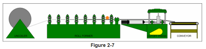
On the machine depicted in figure 2-7, the cut off die is moved by a ball screw actuator. A rotary servo motor is mounted to the back of the actuator and the shafts are coupled via a spline coupler. This tight mechanical coupling provides very accurate positioning. The control system in this case is matching speed and position between the material and the die.
Summary
Most roll forming lines are comprised of one of four basic machine application types. The rest are either very special applications, or they are a mix-and-match setup of the four basic types. For the purpose of continuity and ease of understanding, AMS Controls categorizes machine applications in this way to allow us to convey a general understanding of a machine’s functions in just a few words.
Each roll forming application type has its pros and cons, balancing cost, accuracy and throughput. The faster and more accurate a system must be, the more expensive it is likely to be. Closed loop systems are usually more accurate than open loop systems, but they are also more expensive.
