


XL200 Error Codes
Beginning with version 2 software, the XL200 series controller generates text-based error codes, along with a specific error number.
The controller does not display much in the way of troubleshooting information along with the code, because generally it’s very difficult to predict how customers will use the controller. Different machine types will generate the same error codes for different reasons.
Wherever possible, we’ve tried to describe the errors in layman’s terms and offer some suggestions for troubleshooting the actual nature of the problem, as well as offer some possible solutions.
001 – EPROM checksum test failure.
When powering up, the controller checks the boot code and operating system stored in the Flash EPROM. If certain codes don’t match, this error will result.
Cause
- This error is usually seen after attempting to flash new software into the controller. During the flash download process, some data was corrupted due to poor transmission quality.
- A board-level hardware failure has corrupted the data in the controller Flash EPROM.
Remedy
- Re-attempt the software flash.
- If flashing software from a laptop, be sure the laptop is on AC power and not battery power. Many laptops go into a “power save” mode while on battery power. The COMM ports on the laptop could be operating at a lower power level.
- Try using a shorter communication cable. This cable length should be ≤ 6′ (1.8 m). Be sure to remove the “B” connector from the back of the XL200 controller. Eclipse communication can interfere with the flash process.
- Contact AMS Controls Technical Support for a repair.
002 – Customizing switch error.
Physical DIP Switches are found on the top of v1 – v3 hardware models. Later v4 hardware uses “software switches” accessed by pressing and holding the Setup key on the XL200 keypad. The controller displays this message when the DIP switches have been set to an invalid configuration. The number listed as “Type” indicates the DIP settings. Number each DIP switch in binary beginning with the first switch. For example:
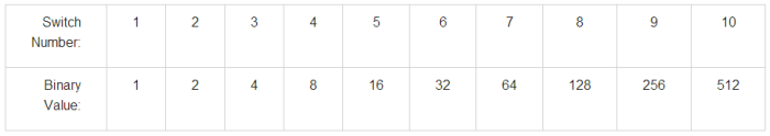
Thus a Type: 25 would indicate that DIP switches 5, 4, and 1 were in their ON position. Based on the specific software model of controller, the machine type could be determined.
The DIP switch settings are defined in the back of the XL controller manuals. They are also listed, along with the controller I/O designations by configuration, here:
XL2XXCL Switch Settings and I/O
Cause
- The controller’s DIP switch settings have created a conflict, such as requiring a feed-to-stop shear with a shear boost output. It should be noted that some “invalid” configurations are intentionally used to “turn off” certain features. The open loop models, for instance, will remove all punch functionality from the controller if a feed-to-stop punch with a punch boost output is selected.
- The user has not fully changed the position of a DIP switch. The DIP switches must be fully transitioned for a change to take effect. Also, the controller power must be cycled before the controller will “see” the change.
- There is a board-level hardware failure in the XL200 controller.
Remedy
- Compare the switch settings in the charts to the desired machine function. Contact AMS Controls Technical Support for help.
- Use a pen tip to fully position DIP switches so they are completely transitioned from their old state to the new.
- Contact AMS Controls Technical Support for a repair.
003 – Configuration data has changed.
This message alerts the user that the controller will be set to factory defaults.
Cause
- Changing certain machine configuration (DIP) switch settings will cause this message to appear on the next power up test. DIP switches change the parameter structure of the controller, and the software functionality in significant ways. It could be unsafe to retain old parameters due to the new machine configuration.
- Changing the software model or version in the Flash EPROM will cause this message to be displayed. During the flash process, critical information from the old software model/version is erased and overwritten. All controller settings must return to factory default.
Remedy
- In the event a DIP switch setting was changed by mistake:
- Do not press the CE key.
- Power down the controller.
- Re-set any changed DIP switches to their original positions.
- Turn controller power back on.
- Once a XL200 controller’s software model/version is overwritten via the flash process, it can not be “recovered”. The controller must be re-parameterized. Contact AMS Controls Technical Support for assistance.
For more information on XL200 DIP switch and machine configuration settings, please see the DIP Switch Configuration article.
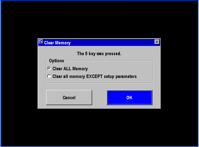
004 – The 5 key was pressed. Record memory will be cleared.
Holding the 5 key on the controller keypad during power up signals the system to clear memory. In older model series (MP300 and XL100), this was a common troubleshooting practice to eliminate corrupt memory due to electrical noise.
The XL200 series hardware and software are vastly improved over its predecessors. In our experience, this model is not susceptible to memory corruption due to electrical noise, assuming the controller is properly wired and installed.
Still, unexpected software problems may occur that can corrupt controller memory. Clearing memory should eliminate the problem until the particular software function that caused the problem is called again.
These kinds of problems are exceedingly rare. Before clearing memory, always consult with an AMS Controls Technical Support Specialist.
In software versions prior to 2.37.00 and 3.01.00, clearing memory set all parameters back to factory defaults, and cleared out all user data. In later versions, this message was removed, and the user is now presented with an option:
Memory is usually corrupted when data is written into a record. Since parameter records are only written when the user changes a parameter and presses the Enter key, it’s extremely unlikely that a parameter can become corrupted. Also, the controller displays this information to the user, so if the data was corrupt, it would show up on the screen.
Since hand-keying data into the controller is a slow and tedious process, and because corrupting parameter data is extremely unlikely, the user is given the option to just clear record data without clearing setup parameters.
In any case, whether the controller is loaded with old or new software, the user can always choose to either Cancel the memory clear, or simply turn off controller power, and then power the system back up normally without clearing memory. It’s always a good idea to maintain an up-to-date record of all controller parameters, tool data, settings, etc.
Eclipse users should have this data automatically backed up within the Eclipse system. Always verify this is true before proceeding with a memory clear.
005 – Invalid EPROM bit code.
This message appears when a XL200 series controller is loaded with an invalid software model.
Cause
The user has received an improperly formatted controller software model flash file.
Remedy
Contact AMS Controls Technical Support to verify the flash file received from AMS Controls is correct for the desired controller model.
006 – Invalid communication hardware detected.
This error relates to the communication port hardware on the XL200 controller.
Cause
The controller has detected a problem with the hardware on one of the communication ports.
Remedy
Contact AMS Controls Technical Support for a repair.
007 – Power was turned off while in the run mode.
The XL200 controller lost power while in the Run mode.
Cause
- Intermittent termination points on A1 and A2 of the controller.
- Loose A terminal connector.
- Bad 24 VDC power supply.
- Bad step-down control voltage transformer, or wiring from the transformer to the system.
- An intermittent short in the system wiring, where machine vibration aggravates the condition.
- Brown-out conditions in the plant. Dips in the incoming 3-phase power could lower the incoming voltage to the XL200 to the range where the controller is forced into power-down mode.
- Component failure on the XL200 CPU board.
Remedy
- Check the wires at A1 and A2 of the XL200. Verify the wires are properly stripped and terminated at both ends.
- Re-seat the A connector. Be sure the hold-down screws are screwed into place.
- Replace 24 VDC power supply.
- Monitor voltage from the transformer, check wiring and termination points.
- Monitor 24 VDC or 120 VAC for the system. Verify constant voltage within operational limits (± 10%).
- Install an Uninterruptible Power Supply (UPS) between the 120 VAC from the step-down control transformer and the rest of the system. Use a unit with a 5 minute battery backup.
- Contact AMS Controls Technical Support for repair.
008 – The setup lockout switch is on.
This message is displayed whenever the user attempts to change a setup parameter while the Setup Lockout input is active.
Cause
Management has decided to lock out critical machine parameters from the operator or casual users. The reasoning is that machine setup parameters should reflect the physical reality of the equipment. Unless reality is changing, setup parameters should not change.
Most setup parameters are locked out by the Setup Lockout input. Some parameters are considered “Operator Parameters” and affect how the machine halts automatically during production. These parameters are not locked by the input.
Coil Verification is also tied to this input. If the machine is integrated with Eclipse, material codes for production orders and coils are checked against each other to ensure the right material is used to produce a given order. Turning the Setup Lockout input OFF allows the user to override the material called by the production order in cases where an executive decision must be taken based on demand and availability.
Typically, the Setup Lockout is controlled by a key switch, but it can also be set through a virtual keypad via alpha-numeric code on a Human Machine Interface (HMI).
Remedy
Turning off the key switch, or entering the appropriate code in the HMI will allow the user to edit all controller setup parameters. Eclipse users can explore options such as saving setup libraries based on product, speed, or material. Machine operator can then pull down entire setup lists from the system, as opposed to editing individual setup parameters – thereby allowing setup changes based on machine/production needs, while preventing mistakes through manual entry. Contact AMS Controls Technical Support for details.
009 – Coils locked out by Eclipse.
This message can sometimes be seen when entering the Production Data\Coil Inventory menu.
Cause
The XL200 series machine controller is designed to be integrated with the Eclipse Production Management System. There could be times when the machine operator and Eclipse are attempting to access certain editing menus at the same time. To prevent problems from occuring, only 1 “user” (the operator or Eclipse) can be allowed to edit those menus at any given time.
When using the Coil Verification functionality in the AMS system, this message will be displayed after the operator loads a new coil into the XL200 controller, and then attempts to access the Coil Inventory menu. If this message is seen, Eclipse is currently trying to send the material code data for the recently loaded coil to the controller for verification purposes.
Remedy
Wait until Eclipse has finished updating the material code for the recently loaded coil.
In the event the controller gets “hung up” in this state, try the following steps:
- Cycle controller power.
- Unload, then reload the same coil.
- Verify all current controller setup parameters are recorded in Eclipse, then clear memory.
If the Production Data\Coil Inventory menu constantly hangs up with this message, it could indicate an ongoing communication problem between the XL200 controller and Eclipse. Contact AMS Controls Technical Support to verify communication settings, and network cabling/wiring.
010 – Orders locked out by Eclipse.
This message can sometimes be seen when entering the Program menu.
Cause
The XL200 series machine controller is designed to be integrated with the Eclipse Production Management System. There could be times when the machine operator and Eclipse are attempting to access certain editing menus at the same time. To prevent problems from occurring, only 1 “user” (the operator or Eclipse) can be allowed to edit those menus at any given time.
If the operator makes any changes to the Program menu, as soon as he leaves that menu, Eclipse is notified of the change and the system performs an update. While data is being transmitted to or from Eclipse, the operator is locked out of the Program menu. Once the transmissions are complete, the operator will be given access to the Program menu again.
This is also true when orders are sent to the machine from Eclipse. During this process, the operator will find himself locked out of the Program menu. The more orders that are sent at one time, the longer the operator will be locked out of the menu.
If the operator isn’t patient, or becomes confused and turns the controller power off, it will take even longer to reconcile the order data since the XL200 must now update Eclipse with its current state before Eclipse can continue to download orders.
A similar message will be seen at the Eclipse PC if the scheduler attempts to send/recall orders to/from the machine while the operator is in the Program menu. Eclipse cannot send or recall orders while the controller displays the Program menu.
Remedy
Wait until Eclipse has finished sending orders or updating its order information. The more orders sent/recalled, and the more orders that are at the machine, the longer this process takes. Generally, the entire process only takes a few seconds.
In the event the controller gets “hung up” in this state, try the following steps:
- Cycle controller power.
- Try sending or recalling an order from Eclipse.
- Verify all current controller setup parameters are recorded in Eclipse, then clear memory.
If the Program menu constantly hangs up with this message, it could indicate an ongoing communication problem between the XL200 controller and Eclipse. Contact AMS Controls Technical Support to verify communication settings, and network cabling/wiring.
011 – Patterns locked out by Eclipse.
This message can sometimes be seen when entering the Program\Patterns sub-menu.
Cause
The XL200 series machine controller is designed to be integrated with the Eclipse Production Management System. There could be times when the machine operator and Eclipse are attempting to access certain editing menus at the same time. To prevent problems from occurring, only 1 “user” (the operator or Eclipse) can be allowed to edit those menus at any given time.
If the operator makes any changes to the Patterns sub-menu, as soon as he leaves that menu, Eclipse is notified of the change and the system performs an update. While pattern data is being transmitted to or from Eclipse, the operator is locked out of the Patterns sub-menu. Once the transmissions are complete, the operator will be given access to the Patterns sub-menu again.
This is also true when orders are sent to the machine from Eclipse. During this process, the operator will find himself locked out of the Program\Patterns sub-menu. The more orders and punch patterns that are sent at one time, the longer the operator will be locked out of the menu.
If the operator isn’t patient, or becomes confused and turns the controller power off, it will take even longer to reconcile the order data since the XL200 must now update Eclipse with its current state before Eclipse can continue to download orders and patterns.
Remedy
Wait until Eclipse has finished sending orders and patterns or updating its pattern information. The more patterns sent/recalled, and the more patterns that are at the machine, the longer this process takes. Generally, the entire process only takes a few seconds.
In the event the controller gets “hung up” in this state, try the following steps:
- Cycle controller power.
- Try sending or recalling an order that calls for a part with a punch pattern from Eclipse.
- Verify all current controller setup parameters are recorded in Eclipse, then clear memory.
If the Program menu constantly hangs up with this message, it could indicate an ongoing communication problem between the XL200 controller and Eclipse. Contact AMS Controls Technical Support to verify communication settings, and network cabling/wiring.
012 – Setups locked out by Eclipse.
This message can sometimes be seen when entering a sub-menu within the Setup menu.
Cause
The XL200 series machine controller is designed to be integrated with the Eclipse Production Management System. There could be times when the machine operator and Eclipse are attempting to access certain editing menus at the same time. To prevent problems from occurring, only 1 “user” (the operator or Eclipse) can be allowed to edit those menus at any given time.
If the operator makes any changes to a sub-menu with the Setup menu, as soon as he leaves that menu, Eclipse is notified of the change and the system performs an update. While data is being transmitted to or from Eclipse, the operator is locked out of the Setup sub-menu. Once the transmissions are complete, the operator will be given access to the Setup sub-menu again.
This is also true when setup parameters are sent to the machine from Eclipse. During this process, the operator will find himself locked out of any Setup sub-menu.
If the operator isn’t patient, or becomes confused and turns the controller power off, it will take even longer to reconcile the setup parameter data since the XL200 must now update Eclipse with its current state before Eclipse can continue to download setup parameters.
A similar message will be seen at the Eclipse PC if the scheduler attempts to upload/download setup parameters to/from the machine while the operator is in the Setup menu. Eclipse cannot upload or download setup parameters while the controller displays the Setup menu.
Remedy
Wait until Eclipse has finished uploading or downloading Setup information. Generally, the entire process only takes a few seconds.
In the event the controller gets “hung up” in this state, try the following steps:
- Cycle controller power.
- Try uploading setup parameters (Eclipse\Maintenance\Machine Setup Parameters), or downloading a Setup Library from Eclipse.
- Verify all current controller setup parameters are recorded in Eclipse, then clear memory.
If the Setup menu constantly hangs up with this message, it could indicate an ongoing communication problem between the XL200 controller and Eclipse. Contact AMS Controls Technical Support to verify communication settings, and network cabling/wiring.
013 – Tools locked out by Eclipse.
This message can sometimes be seen when entering the Setup\Tool Data menu.
Cause
The XL200 series machine controller is designed to be integrated with the Eclipse Production Management System. There could be times when the machine operator and Eclipse are attempting to access certain editing menus at the same time. To prevent problems from occurring, only 1 “user” (the operator or Eclipse) can be allowed to edit those menus at any given time.
If Eclipse is uploading Tool Data information, or downloading a Tool Library, the operator is locked out of the Setup\Tool Data menu. Once the transmissions are complete, the operator will be given access to the Setup\Tool Data menu again.
If the operator isn’t patient, or becomes confused and turns the controller power off, it will take even longer to reconcile the Setup\Tool Data information since the XL200 must now update Eclipse with its current state before Eclipse can continue to download tooling parameters.
A similar message will be seen at the Eclipse PC if the scheduler attempts to upload/download tooling parameters to/from the machine while the operator is in the Setup\Tool Data menu. Eclipse can not upload or download tooling parameters while the controller displays the Setup\Tool Data menu.
Remedy
Wait until Eclipse has finished uploading or downloading Setup\Tool Data information. Generally, the entire process only takes a few seconds.
In the event the controller gets “hung up” in this state, try the following steps:
- Cycle controller power.
- Try uploading Tool Data parameters (Eclipse\Maintenance\Machine Tool Setup), or downloading a Tool Library from Eclipse.
- Verify all current controller setup parameters are recorded in Eclipse, then clear memory.
If the Setup\Tool Data menu constantly hangs up with this message, it could indicate an ongoing communication problem between the XL200 controller and Eclipse. Contact AMS Controls Technical Support to verify communication settings, and network cabling/wiring.
016 – Comm failure on RS422 port.
017 – Comm failure on RS485 port.
018 – Auxiliary device error. Unit: <auxiliary controller network ID> Error: <error text>
019 – Auxiliary communication port error. Unit: <auxiliary controller network ID> Error: <error text>
020 – No gag board found.
021 – Shear dwell not set.
022 – Press dwell not set.
023 – Shear Tool must be defined as Tool 0 on Press 0.
024 – No items programmed.
025 – No orders programmed.
026 – No sheet detected.
027 – E-Stop input is off.
028 – Tool data not programmed.
029 – Punch pattern not programmed.
030 – Wrong coil loaded.
031 – Wrong product code.
032 – Missed printer target.
033 – Missed punch target.
034 – Missed shear target.
035 – Coil end point reached. The cut off point has coasted <distance> past the coil end point mark.
036 – Item not completed.
The operator presses the Increase Quantity button and this error appears.
Cause
An Increase Quantity was requested on a cutlist item that has been completely filled into the part queue, and at least 1 part of the next cutlist item has been filled into the queue. Increase Quantity is no longer an option for this cutlist item.
Remedy
The operator must run the current cutlist item to completion, and then use the Remake function to replace scrap parts on this cutlist item.
037 – No parts to fill in queue.
038 – No press complete input for Press <press number>.
039 – Out of tolerance.
The “Out of tolerance” error indicates the controller has calculated that a cut or punch operation has fallen outside of the programmed Tolerance parameter.
Causes
The cause of the “Out of tolerance” error message varies based on machine application type.
Open Loop Stopping
Each time the XL200 Series controller stops the material for a press operation, the controller checks to see if the stop occurred within the defined Tolerance range. If not, the “Out of tolerance” error is displayed.
The most common reason for an “Out of tolerance” message on this type of machine is due to a large shift in the time it takes for the machine to stop. By default, the XL200 Series controller tests to see how long it takes the machine to stop, then stops the machine early by that time on successive stops. The stopping time for the machine is updated for every press operation in the automatic mode.
- Changing from very long parts to very short parts (or vice versa) can cause some machines to greatly lengthen or shorten their stopping reaction times.
- Mechanical backlash can create large reaction shifts.
Remedies
- Turn on dynamic braking in the inverter used to control material motion.
- Try running the machine in 2-speed mode, where the material shifts into a slow speed before stopping.
- Remove all mechanical backlash from the machine: i.e. tighten chains, replace couplers, replace worn gears, etc.
- Try using the Bump-Into-Tolerance feature.
Closed Loop Stopping
In the closed loop feed-to-stop application, the XL200 Series controller creates a motion profile that brings the material to 0 fpm (0 mpm) before firing the press. The controller waits up to 1 s for the material to get into tolerance before displaying the “Out of tolerance” error.
- Mechanical backlash can cause 2-encoder systems to “continue moving” after the servo motor has stopped.
- Tuning problems in the servo system can cause the servo motor to oscillate on stand still.
- Based on certain parameters, the press can be fired while the material is decelerating to a stop. If the press is contacting the material too soon, the servo might still be trying to drive the material into position.
Remedies
- Remove all mechanical backlash from the machine: i.e. tighten chains, replace couplers, replace worn gears, etc.
- Check the tuning of the servo system. Reduce motor oscillation as much as possible. Contact AMS Controls Technical Support or the servo manufacturer for help.
- Contact AMS Controls Technical Support for help.
Closed Loop Flying Die
- Contact AMS Controls Technical Support for help.
040 – Stopping timeout.
041 – Hole detect failure.
043 – Tool 1 must be used with Alternating Punch option.
044 – Value out of range. Upper Limit: <upper limit value> Lower Limit: <lower limit value>
045 – The status must be Ready.
046 – The status must be Ready or Next.
047 – The status must be Ready or Skip.
048 – The line must be halted.
049 – Decrease quantity error.
050 – Increase quantity error.
The operator scans a scrap code with the bar code scanner and this message appears.
Cause
The operator attempted to scan a scrap code to increase quantity on a cutlist item that was completely queued. Since no more parts from that cutlist item were available to load into the Part Queue, and because this situation could have lead to other cutlist items being loaded into the queue, the controller can not queue up scrap parts for the current item.
Remedy
After the last parts of the current item are complete, the operator should use the Remake feature to replace scrap parts.
051 – Invalid pattern operation.
052 – Can not delete while in run mode.
053 – Part is less than minimum part length.
054 – The coil inventory is empty.
055 – Order not found.
056 – Pattern not found.
057 – Pattern already exists.
058 – Tool already exists.
059 – The maximum number of holes per part was exceeded.
060 – Can not delete an order or item that is part of a bundle printer cut list.
061 – Can not convert this pattern to a Macro. It contains operations with references other than Lead Center or Trail Center.
062 – Correction factor out of range.
063 – A negative shear reaction time was calculated.
064 – The calculated reaction time is too long.
065 – Memory test failure.
066 – Memory is below 5%.
067 – Memory is below 10%.
068 – Printer communication failure.
069 – Printer missing AMS ID.
070 – Asychronous Printer Queue is full.
071 – Drive not responding to analog command voltage.
072 – Exceeded maximum slippage between line and motor encoder.
073 – Exceeded maximum lag compensation time.
074 – The line is running too fast for the die to perform this operation.
075 – Shear cycle aborted. For safety, the button must be held until the cycle is complete.
076 – EPROM BOOT checksum test failure.
077 – EPROM APPLICATION checksum test failure.
078 – Axis <axis number> is not in position.
079 – Axis <axis number> is not programmed.
080 – Axis <axis number> is not active.
081 – Axis not enabled. Axis must be in Phase 4, with power applied and enabled.
082 – Axis <axis number> command position out of range.
083 – The motor must be disabled.
084 – Possible material jam up.
085 – Remake Item error. Can not remake more parts than are currently done.
086 – Material Code not found. Material codes are locked by Eclipse.
087 – Product Code not found. Product codes are locked by Eclipse.
088 – No material code programmed.
089 – No product code programmed.
090 – Length Verification Error. Programmed Length: <length programmed> Measured Length: <length measured by system>
091 – Multi-Angle Shear Programming Error. Alternating, Mirror part options and ‘Center’ Machine Y Reference are not allowed.
092 – Opposing Axes are not programmed correctly for Axis <axis number>.
093 – Network ID not programmed correctly for Axis <axis number>.
094 – Multi-Axis Command Failed for Axis <axis number>.
095 – Please wait for Eclipse to validate this coil. If the Eclipse PC is offline, this condition can be overridden by turning off the Setup Lockout key.
096 – All Machine Axes are not in position. This operation has timed out.
097 – No Shear Up Complete input.
098 – Cannot delete an order containing an item that has a status of Work, Next, or Fill.
099 – Invalid Part Print Message. The current print message contains data that is not supported for print-on-part printers.
100 – Out of Sync Halt. The measurements reported by the QC100L are out of sync with the programmed values.
101 – Marginal Sync Halt. The measurements reported by the QC100L may be out of sync with the programmed values.
102 – No measurement has been received from the QC100L within the No Measurement Stop Distance Setup Parameter.
103 – Alternating Press Tool Definition Error. Must have Tool 1 defined with Press 1 and Tool 2 defined with Press 2.
104 – Invalid Data Entry. There are no records in the list with a value that matches this entry.
105 – SERCOS hardware initialization error.
106 – Fatal Memory Test Error. The controller has detected an unrepairable condition and will automatically clear all memory.
107 – PLC Communication Failure. The PLC will be taken Offline. Error: <error text>
108 – Message from PLC: <message text>
109 – The PLC is offline or has invalid configuration data.
110 – Text string too long. Maximum # of characters: <number>
111 – The data entered doesn’t match what was expected. Expected data: <message text>
112 – RAM Battery Backup Voltage Error!!! Call AMS Controls at 1-800-334-5213 for details.
Cause
The controller battery requires replacement. See our documentation on battery replacement to resolve.
113 – Front Shear Tool Not Programmed.
114 – Front shear tailout.
Actual Error Text: The remaining material may need to be cut into final part lengths and the item quantity may need to be manually decremented.
Cause
This error occurs when a Tailout condition occurs after a Front Shear operation has taken place. Since the XL200 Series controller automatically counts the remaining material in the machine as scrap on a Tailout condition, the operator is prompted to manually cut the last piece(s) from the remaining material and use the Decrement Quantity feature on the controller to properly account for the last piece(s).
Remedy
Based on the machine type part produced, the operator should manually jog final cut points under the shear and fire the shear manually to cut the last piece(s) from the coil. After all pieces are produced, the operator should use the Decrement Quantity feature to account for the last good parts produced.
