


Troubleshooting Encoder Alignment
Encoder and material tracking problems account for most product length variations on computer controlled roll forming lines. From the perspective of a length control system, all information regarding the material – direction, speed, distance traveled – comes from a single point, where the encoder measuring wheel contacts the material. Proper tracking of the encoder measuring wheel is therefore critical to machine performance.
Variance can come from sources other than the measuring system. However, these sources are less likely, and tend to be specific to the machine application type. The encoder system should always be examined first when troubleshooting length variance.
This troubleshooting article has been developed specifically for the AMS Controls Encoder. Troubleshooting non-AMS Controls encoders is not covered in this article.
Note: The procedures described in this handbook must be performed only by trained, certified industrial electricians. While AMS Controls has taken all reasonable care to develop safe procedures, it accepts no responsibility for injuries, damages, death or destruction to persons or equipment caused as a result of not closely following these instructions.
Removing Power from the System
When required to remove power from the system you must, turn the disconnect on the Auxiliary Electrical Box to the OFF position. This removes power from all the aux box components except the disconnect itself.
DANGER! Turning the power off at the main operator’s station does not remove all power from the system.
Check the Encoder Wheel for Perpendicular Alignment
Use a machinist’s square to check an encoder wheel for perpendicular alignment. The encoder wheel needs to be square (perpendicular) to the material surface on which it rides to ensure proper tracking.
Equipment Required
- Machinist’s square
Note: Carpenter’s squares are not square enough to be used to test for perpendicular positioning. It is important to have a proper machinist’s square for this test to be accurate.
Check for Perpendicular Alignment
- Place the base of the machinist’s square on the material surface that the encoder contacts.
- Slide the square toward the side of the encoder wheel until it just makes contact with the encoder wheel.
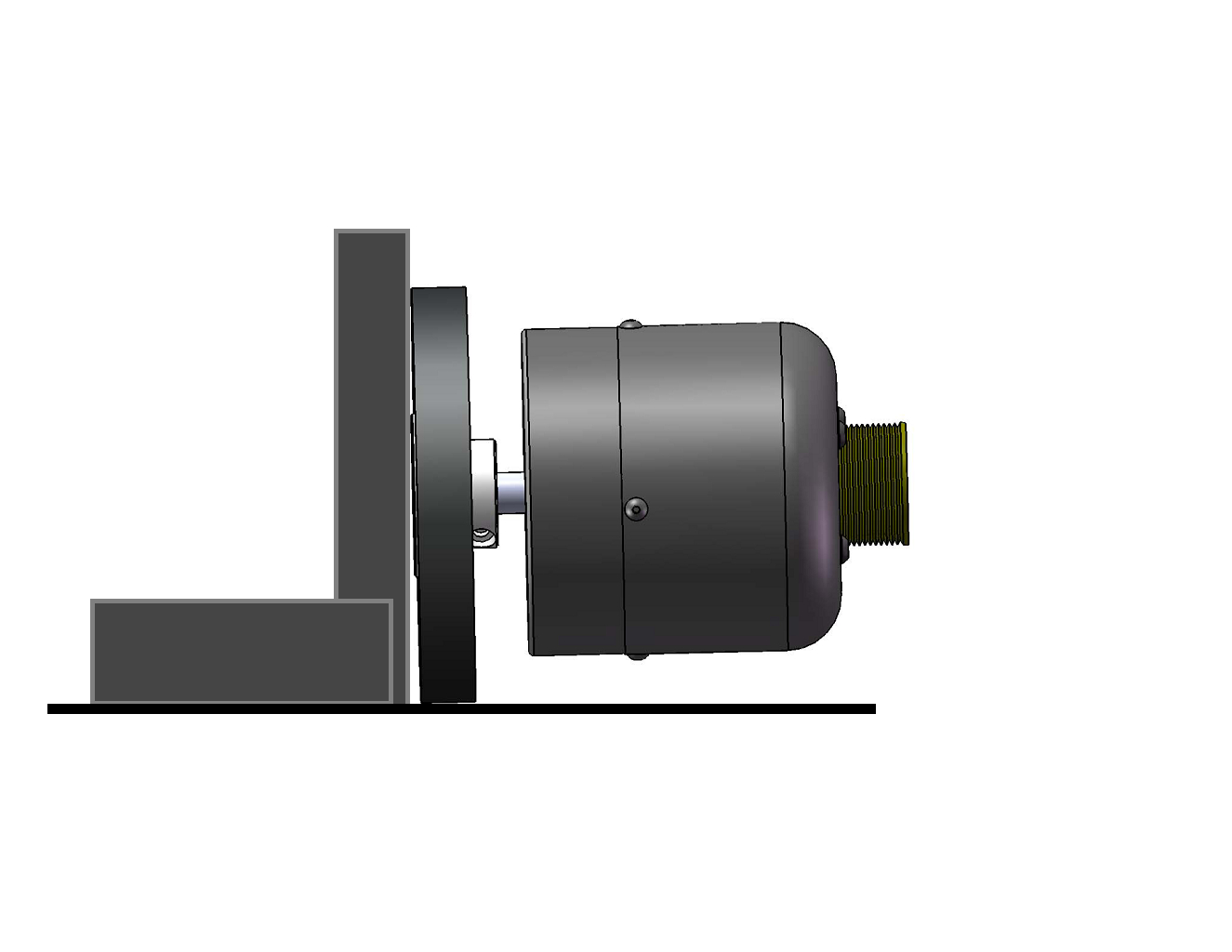
Figure 1: Machinist’s Square Showing a Gap, Indicating the Encoder Wheel is not Perpendicular
Examine the wheel and square from the front (looking head-on at the rim).
- If there is no gap between the encoder wheel and the machinist’s square, the encoder wheel is perpendicular to he material surface.
- If any gap is visible between the encoder wheel and the machinist’s square’s edge, the encoder wheel is not perpendicular to the material surface.
Check the Encoder Wheel for Parallel Alignment
Use a straight-edge and calipers to check an encoder wheel for parallel alignment.
Equipment Required
- Straight-edge or metal ruler
- Calipers
Check for Parallel Alignment
Lay the straight-edge along the wheel in the direction of material flow and draw a line along the length of the straight-edge.
Figure 2: Testing for Parallel Alignment
2. If the measuring wheel is out of alignment, the error will be exaggerated by this line.
3. Using a set of calipers, the distance from each end of the line to the edge of the material should be measured.
The difference between the two measures should be less than 0.010” (0.254 mm) over 12” (304.8 mm).
If the error is greater than 0.010” (0.254 mm), the encoder bracket assembly should be realigned.
Note: Alignment should be rechecked each time the encoder bracket is loosened and retightened.
Oscilloscope Test
Use a two-channel Oscilloscope (O-scope) to verify the appearance of the signals coming from the encoder. Use the O-scope any time that:
- There are no counts coming from the encoder.
- You suspect the counts from the encoder are incorrect.
- Noise may be interfering with the counts.
Equipment Required
- Probe cables
- Oscilloscope (two channel with invert and add functions)
Note: To properly view the encoder signals, you must use a two-channel O-scope with both invert and add functions. Without these functions, your results will not match what is shown below.
Perform the O-Scope Test
- Connect the O-scope’s ground reference to the encoder’s ground circuit.
Note: To perform this test, you must use an encoder (or digital) ground. Grounding this way avoids “floating” at the same voltage, so the signal will be visible.
- Connect one probe to the A-channel.
- Connect the second ground reference of the scope to the encoder’s ground circuit.
- Connect the second probe to the B-channel. The PC screen displays a wave form for the encoder signal:
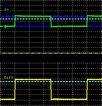
Figure 3 : Encoder Wave Form Displayed on the Oscilloscope (O-scope)
The display is typical of quadrature, showing the A-channel and B-channel 90° out of phase with each other, with the B-channel transitioning halfway through the A-channel’s wave.
– A leading B (A to the left of B) indicates the encoder is moving in the positive (forward) direction.
– B leading A (B to the left of A) indicates the encoder is moving in the negative (reverse) direction.
The smooth squared-off forms of the wave indicate clean pulses; spiking, wobbly or jagged waves indicate noise interfering with the signal. If you have spiking, wobbly or jagged waves, contact AMS Technical Support for further guidance.
Verify Encoder Counts (10-Turn Test)
Perform a 10-turn test to verify that an encoder is counting accurately. This test checks the internal hardware of the encoder, the cable from the encoder to the control system and the encoder circuits on the machine controller.
If all hardware is “good” as tested, but length variance persists, check the encoder tracking.
