


Encoder Tracking and Mounting
Accurate and consistent part lengths are crucial to quality control in roll forming processes. Even if parts are produced in tolerance, a batch of parts that are inconsistent in length will be more rigorously scrutinized by the end-user than a stack where the ends of all the parts line up.
Encoder and material tracking problems account for most product length variations on computer controlled roll forming lines. From the perspective of a length control system, all information regarding the material – direction, speed, distance traveled – comes from a single point, where the encoder measuring wheel contacts the material. Proper tracking of the encoder measuring wheel is therefore critical to machine performance.
Variance can come from sources other than the measuring system. However, these sources are less likely, and tend to be specific to the machine application type. They are more appropriately addressed by machine application in a separate article, rather as a comprehensive article on length control. Also, since encoders are present on most computer controlled roll forming machines, and because the problems associated with encoder tracking and mounting are similar in each application, the encoder system should always be examined first when troubleshooting length variance.
For technicians, maintenance and engineering, locating the source of a length variance can be a daunting task. This article will help educate the troubleshooter and describe methodologies for correctly implementing the encoder system for a roll former, as well as ‘best practices’ for encoder systems on computer controlled roll forming lines.
Basic Encoder Function
A rotary encoder is a device that transmits digital pulses as a shaft is turned. A wheel is coupled to the end of the shaft, and that wheel rides on the surface to be measured. As material flows under the wheel, the wheel turns the shaft, and the electronics inside the encoder transmit pulses to a control system. A typical encoder and its associated measuring wheel are depicted in figure 1-1.
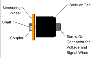
Figure 1-1
Inside the encoder there is a small disc typically made of plastic or glass. This disc might have hundreds, or even thousands, of slits cut in the outside diameter (see figure 1-2). As the measuring wheel turns, it spins the shaft of the encoder. The disc is housed so the outside edge moves through an infra-red beam. As the slits in the disc move through the beam, the light is chopped into pulses that are picked up by a sensor located behind the disc.

Figure 1-2
The light pulses are converted electronically into digital pulses and sent to the length control system (figure 1-3).
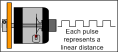
Figure 1-3
The control system must be programmed with the distance that is passing for each pulse. This is the linear distance measured by the wheel per pulse from the encoder, or resolution.
Quadrature
Quadrature is a method of looking at a bi-directional encoder signal and counting 4 pulses for every 1 pulse received, allowing higher resolution and greater accuracy from a lower resolution encoder. It is the directionality of the encoder signals that allows quadrature counting to be implemented.
With quadrature, there are two signal channels, normally called A and B. The encoder’s disc and read head are arranged so the square wave signal from the A and B channels are 90 degrees out of phase. In figure 1-4 time flows from left to right. The A signal (blue) turns on before the B signal (green), indicating forward motion.
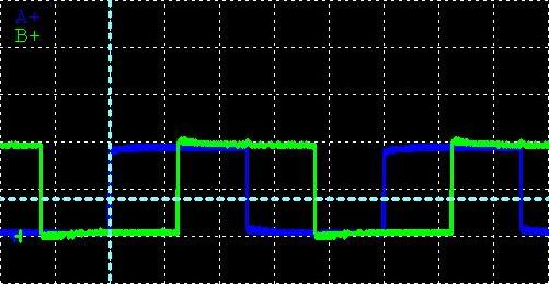
Figure 1-4
When B leads A (figure 1-5), reverse direction is indicated. These signals can be seen using an oscilloscope.
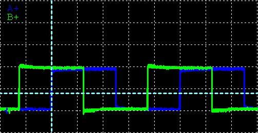
Figure 1-5
Circumference and Resolution
Resolution is calculated by dividing the circumference of the measuring wheel by the number of pulses per revolution generated from the encoder. Circumference is the total linear distance traveled for one revolution of the wheel, and is based on wheel diameter. It’s calculated by multiplying the wheel diameter by pi, a mathematical constant approximately equal to 3.14. Once the circumference of the wheel is known, resolution can be calculated by dividing the circumference by the number of pulses per revolution from the encoder.
Example 1:
An encoder and measuring wheel are installed on a roll former. The wheel is 3.815” in diameter, and the encoder is rated for 8000 pulses per revolution. The circumference equation follows:
C = π · D
C = Circumference
π = 3.14
D = Diameter
π · 3.815” = 11.985”
Resolution is calculated by dividing the circumference of the measuring wheel by the number of pulses per revolution (ppr) from the encoder. The resolution equation follows:
R = C / PPR
R = Resolution
C = Circumference
PPR = Pulses Per Revolution from Encoder
11.985” / 8000 ppr = 0.001498” per pulse
Encoder Measuring Wheels
In example 1, the measuring wheel is assumed to be concentric (round). Even slightly out-of-round wheels can generate inconsistent results, usually in the form of long-short pieces in cases where part lengths are exact multiples of the measuring wheel circumference. For example, to guarantee the error due to non-concentricity to be less than 0.001” (0.0254 mm), the radius of the measuring wheel must be within 0.00016” (0.004064 mm).
For best results, encoder shafts should always be directly coupled to the measuring wheel, and the wheel should always ride directly on the material. Often, maintenance or engineering will construct a bracket that uses a flex (“zero backlash”), dual-spring, or spline couplers to isolate the encoder from the measuring wheel. This is usually done to protect the encoder from material crashes. Encoders are relatively cheap, and if the material has a tendency to crash in a certain area of the machine, this should be a flag that further engineering (or maintenance) of that machine element is required.
All too often, these couplers create long delays in troubleshooting problems with the encoder system. Flex couplers can break and allow backlash, but not so much that the damaged portion of the coupler is easy to see. The inner spring of a dual-spring coupler will break allowing significant backlash, but the problem can’t be seen until the coupler is physically removed. Spline couplers are notorious for inducing backlash over time, as the spider insert begins to wear.
Machine builders will sometimes couple the encoder shaft to a roll tool or pinch roll. This always results in poor encoder tracking. Unless the rolls are designed to ensure perfect tracking between the roll and material movement (i.e. embossing wheels), it is far better to use a separate, low-mass measuring wheel.
Measuring wheels should suit the application. Painted materials like those used for products that will be visible to the consumer in their finished form usually require a measuring wheel that will not mark the material. Metal wheels are generally not acceptable for such processes. There are several types of polymer wheels that are slick enough to avoid scratching the formed part, yet offer enough friction to track well. In these situations, an encoder should be chosen that offers a very low-friction bearing assembly, so there is less friction in the bearing than between the wheel and the material. Encoder shaft bearings that produce too much drag will cause the wheel to slip.
Hardened steel makes an excellent measuring wheel. It can be knurled so that it “bites” the material. This type of wheel will generally mark the material, but if this is aesthetically acceptable for the finished product, less tension is required to track the material. The marks left on material by a knurled wheel can be beneficial as a quick check for tracking quality. Often, a finished part can be held under the glare of shop lights to make the “tic” marks left on the steel visible to the naked eye. The quality of the encoder tracking can be easily checked based on the type of tracking patterns left on the steel.
Magnetic wheels are often used for steel forming, but the wheels tend to collect debris that can scratch paint, or minimally make the encoder wheel out-of-round. While rubber wheels might be commonly used by machinery builders, they should be avoided in applications requiring accuracy and repeatability. Rubber does not consistently compress, and is sensitive to temperature. On hotter days, rubber will expand and compress more. On colder days, rubber contracts and compresses less. These variances cause a change in the effective resolution that will result in part length variances.
Length Control System Calibration
While calibration features in a control system can help center tolerance error, proper alignment and good tracking are crucial to eliminating variance. Calibration is only useful in removing a consistent amount of error. If machine operators or maintenance personnel are attempting to chase variance by calibrating the machine, they are wasting time and material. Though variance could be caused by improper parameterization or poorly written software, it usually comes from a physical (real world) source. In any of these cases, calibration is not the solution to the problem.
In example 2, a machine has two problems; the part lengths are coming out long on average, and the lengths vary more than is acceptable for the defined part tolerance. Calibration removes the average error in length, but can not make the machine more consistent.
Example 2:
In figure 1-6, a 20 part sample is run from a roll forming machine and plotted on a graph. The lengths are examined to determine the longest and shortest parts. The target length is 60.000” (1524 mm), but the sample shows lengths ranging from 60.150” (1527.81 mm) to 60.400” (1534.16 mm).
Even though the parts are coming out an average of 0.229” (5.817 mm) long, the actual variance of the lengths produced is only ± 0.125” (3.175 mm).
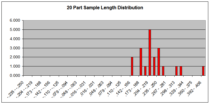
Figure 1-6
In order to calibrate the system, the average part length, 60.229” (1524 mm) must be used. If the length control system does not have an on-board trim correction feature, the measured length is divided by the programmed length to calculate a correction percentage. This percentage is multiplied by the control systems resolution parameter to calculate a new, corrected resolution.
Once the system has been corrected, a new 20 part sample is run and plotted on a graph (figure 1-7). The calibration of the length control system allows the error to be centered around the target value, however, the variance is not affected by the calibration procedure.
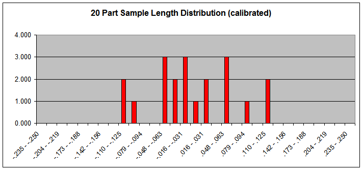
Figure 1-7
In this case, the defined tolerance for the product is ± 0.063” (1.6002 mm). The part lengths are still unacceptable. Something else must be done to eliminate the length variance.
Example 2 uses a part sample size of 20 pieces to establish the base machine consistency. This is important. Small samples of 1 – 2 parts, randomly selected from a production run, do not give the observer an accurate view into the capability of the machine. Too often, assumptions about length patterns are made and time is wasted chasing down problems that don’t exist. Measuring parts in the order produced from the machine can also help in troubleshooting a variance, as patterns can appear that direct the troubleshooter to a specific area or machine element.
Encoder Bracket-assembly Mounting and Orientation
There are two major concerns when it comes to mounting an encoder bracket on a roll former; bracket stability and material stability. The single most important feature of an encoder bracket is that it must be “solid”. Often, a bracket will tension the measuring wheel and encoder to the material with air or a spring to allow some vertical movement of the material during the forming process. Vertical displacement is acceptable, so long as that is the only mechanical give in the assembly. Any side-to-side play, or “slop”, in the bracket assembly is totally unacceptable.
The more rigid the bracket mounting, the more forgiving the perpendicular alignment of the wheel to the material can be. Best practices recommend riding the measuring wheel so that it is on a flat surface, perpendicular to that surface. Sometimes, this isn’t physically possible. The part shape, or space constraints, might make perpendicular orientation of the wheel impossible. When this is the case, consistent riding of the wheel on a rounded surface, or at an angle to the perpendicular plane is possible, if the bracket allows for zero deflection of the wheel.
On most roll forming machines, the best place to mount the encoder (depicted in figure 1-8 as the orange circle) is near the exit end of the machine by the shear, between the second-to-last and last pass of the roll former. Figure 1-8 shows a typical post-cut roll forming process.
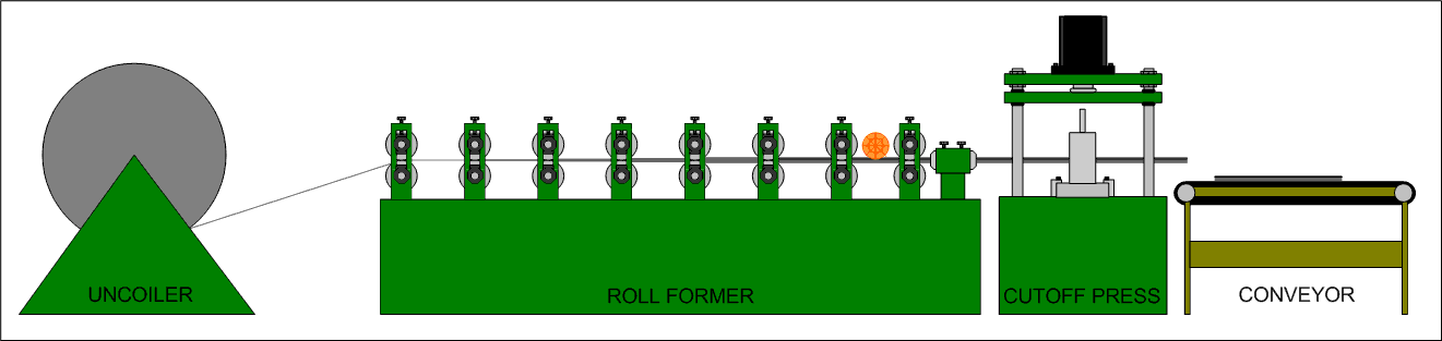
Figure 1-8
Mounting the encoder near the end of the forming process removes error due to material stretch. Usually, the last few passes of a roll former perform very little forming, and are typically used to finish the shape of certain part elements like flanges. This area should be very stable, as material is trapped on either side of the measuring wheel by the roll tooling. The tooling on the final pass, as well as the straightener help to dampen material vibration transmitted from the shearing operation. The material itself should provide a more rigid area for measurement since it has been formed by the machine.
The best possible method to allow for vertical material displacement is direct, vertical pressure on the encoder and wheel. Angular tension requires extra consideration. Many encoder brackets mount to a steel bar, and are designed to allow the bracket to rotate a few degrees around a pivot point (the same bar used for mounting). In this situation, vertical displacement of the material creates an angular displacement of the bracket, forcing the shaft of the encoder to turn, even though no linear material movement has occurred. The angular displacement creates a length error. This type of error is most often seen when material thickness changes, but it can also occur if the material fluctuates vertically during the forming process.
Figure 1-9 demonstrates the problem. If the material moves up, even if the wheel remains in a constant orientation, the shaft of the encoder must rotate to allow for the motion. The encoder will report reverse motion to the control system. Conversely, if the material moves down, the wheel must rotate the encoder shaft forward.
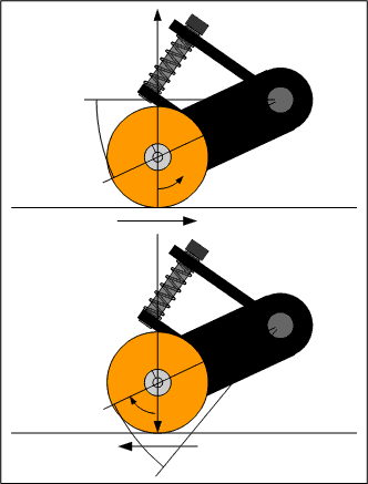
Figure 1-9
For this style of encoder bracket, the best mounting orientation is to lower the mounting bar so the centerline of the bar – and shaft of the encoder – are on the same horizontal plane, parallel to the material as in figure 1-10.
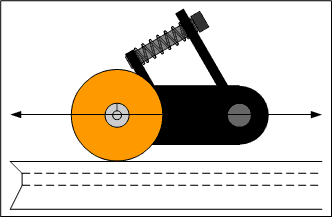
Figure 1-10
The issue of angular displacement creating a linear error still exists with this bracket, but the effects are mitigated by calibrating to a “center” position. Length shifts due to material thickness changes should be slight.
Material Stability
After bracket stability and rigidity, material stability must be considered. If the material is allowed to sag, buckle or hump as it travels past the encoder wheel, the end result is the same as if the encoder bracket is fluctuating. Length control systems view the material as a straight line through the measurement point and all the tooling the system controls. That is, if a length controller fires a punch press and a shear press, the distance between the punch and the shear must be a straight, unchanging line. If the encoder is mounted upstream or downstream from both presses, the extra distance from the encoder to the closest press must also be a straight line. A computer that relies upon a measuring wheel for length and position data can not “see” material fluctuations, therefore it can not account for those fluctuations and they will result in part length variances.
Long distances of unsupported material between the encoder and presses will tend to create a length problem. Gravity is an unyielding force that always creates a bow in any material. Even a welded steel pipe must bow to gravity, if the distance between supporting surfaces is great enough. Assuming the shop floor is flat and level, a dial indicator affixed to a cart can be set to measure the material near one end of an unsupported distance. As the cart is rolled down the length of the material, the pickup for the dial indicator will be dragged across the material surface. At the center of the unsupported distance, the maximum material sag can be measured. This error will be roughly equal to the length error.
Another problem with long sections of unsupported material is bounce from press firings. This can deform the material and change the distance measured. Products that have less rigid final forms will tend to “remember” the shockwave from the instantaneous contact of the press tooling. Even if the material is rigid enough to be immune to such forces, it could bounce and vibrate so hard that it has not settled before the next press firing.
Length control systems that use closed loop servos to position press tooling on-the-fly will suffer greatly from material bounce, especially if that bounce is transmitted to the encoder. If the encoder “sees” the material quickly fluctuate front-to-back, the tooling in the press could be forced to move front-to-back as the system attempts to match material position. This can result in damaged tooling and equipment, or material jam-ups inside the machine.
The most common problem with material/bracket stability (or a bent shaft) is a wobble that causes the measuring wheel to measure a wave, instead of a straight line. The axiom – the shortest distance between two points is a straight line – applies here. Figure 1-11 shows two lines connecting the same two points. One line is straight, and the other is a wave, crossing back and forth across the straight line.
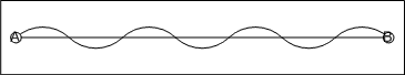
Figure 1-11
The straight line in figure 1-11 measures 14” (355.6 mm). The wavy line measures 17.593” (446.862 mm). If the wavy line is straightened, as in figure 1-12, the difference in length is obvious.

Figure 1-12
A major misconception regarding encoder measuring wheels is “as long as the wheel is in contact with the material, the tracking is okay”. Figures 1-11 and 1-12 illustrate that good encoder tracking is not a simple function of maintaining contact between the measuring wheel and the material. Only through measurement and diligence can an encoder bracket system be aligned such that the encoder and measuring wheel are reporting true material motion back to the length control system.
To understand the problem mathematically, example 3 shows what happens when the measuring wheel is allowed to oscillate, or wobble, down the length of a part.
Example 3:
Figure 1-13 demonstrates the problem of a “sloppy” bracket. The original resolution calculated for this measuring wheel was based on a diameter that is twice the radius (a). If the wheel ever rides up on one corner, the diameter changes based on the new radius (c). Both radii form a right triangle, where the new radius (c) is the hypotenuse of the triangle. Radius c is physically longer than the original radius on which the circumference (and thus the resolution) was calculated.
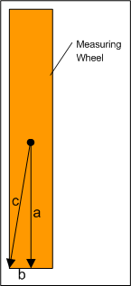
Figure 1-13
In the case of a wheel that wobbles side-to-side, the resolution is constantly changing, but the length measurement system can not sense this error. In this case, the encoder bracket must be locked down. Shims may be necessary, or re-drilling and re-tapping mounting holes could be required to stabilize the setup.
Similarly, the material could be fluctuating under the wheel side-to-side. Such a fluctuation would have exactly the same effect as if the wheel, itself, were moving. Material should be guided and stabilized before and after the measuring wheel. The wheel should be “backed up” by a plate or idler wheel on the opposite side of the material perpendicular to the wheel.
Encoder Alignment
Once the tracking of the measuring wheel is stabilized via the mounting bracket, the wheel should be checked for square and parallel tracking. Square should only be measured using a machinist’s square. Carpenter’s squares are not square enough. The measuring wheel needs to be square (or perpendicular) to the material surface on which it rides (see figure 1-14).
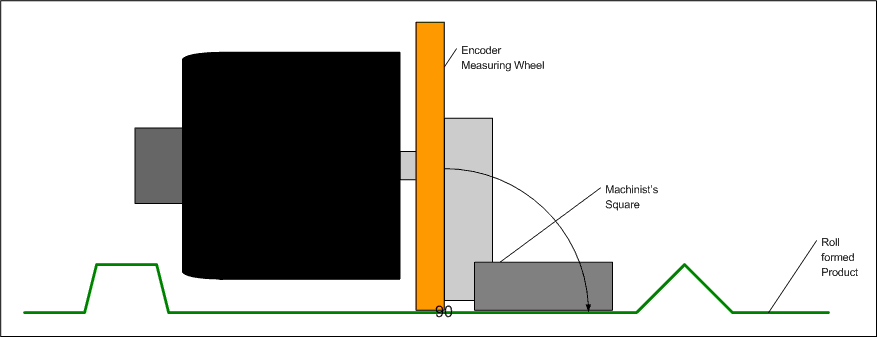
Figure 1-14
When checking for square, there should be no gap between the wheel and the square, or between the material and the square. Both surfaces should be flush with the square.
After checking perpendicular alignment, parallel alignment should be verified. A straight-edge or metal ruler should be used with a set of calipers. Lay the straight edge along the wheel in the direction of material flow and draw a line along the length of the straight-edge, as in figure 1-15. If the measuring wheel is out of alignment, the error will be exaggerated by this line.
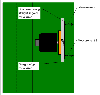
Figure 1-15
Using a set of calipers, the distance from each end of the line to the edge of the material should be measured. The difference between the two measurements should be less than 0.010″ (0.254 mm) over 12” (304.8 mm). If the error is greater than that, the encoder bracket assembly should be re-aligned. Square and parallel alignment should be rechecked each time the encoder bracket is loosened and re-tightened.
Visual Inspection
Knurled, hardened, steel measuring wheels offer the best tracking characteristics for steel. When their use makes sense (aesthetically) for a roll forming application, they should be used.
One of the best features of the knurled measuring wheel is that it usually leaves behind a tracking pattern on the part. Tracking variance due to bracket mounting, material stability, and alignment are immediately visible to the user.
Presented here are some examples of common material tracking issues, from the perspective of observing the tell-tale “tic” marks left behind from a knurled measuring wheel. Figure 1-16 shows a hardened, knurled steel wheel riding on a part. The pattern left on the steel is the same width as the encoder wheel, for the entire length of the part.
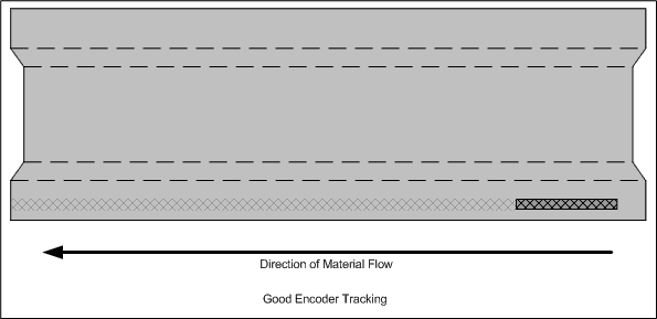
Figure 1-16
If the measuring wheel is not perpendicular to the surface of the material where it rides, the width of the marks left behind will not be consistent with the width of the wheel (figure 1-17).
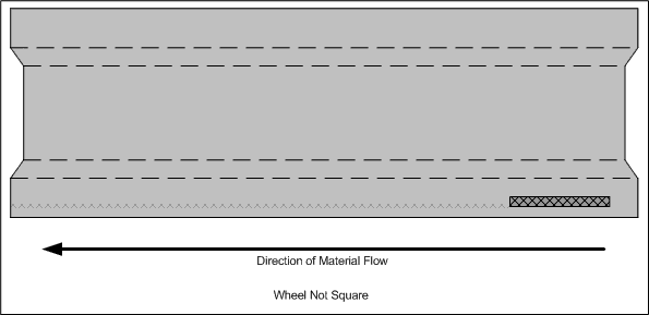
Figure 1-17
The illustration in figure 1-17 shows a very consistent tracking pattern. If the bracket-assembly had mechanical slop, or if the encoder shaft was bent, this pattern would tend to drift back and forth down the length of the part like in figure 1-18.
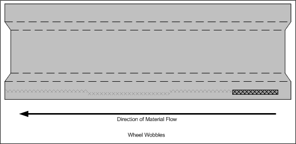
Figure 1-18
Clearly, the encoder mounting bracket assembly must be re-aligned, tightened, and possibly shimmed or re-mounted completely. With this type of tracking, it’s also possible the material itself is not a flat surface. Bent roll former shafts will induce sinusoidal waves along the length of the material. The net effect is the same as if the wheel itself were wobbling.
For a system where the wheel is not riding parallel to the material, the “tic” marks left by the wheel would tend to look more like elongated slashes, as in figure 1-19.

Figure 1-19
Summary
For computer controlled roll forming processes, length variance is most often attributed to material tracking issues. Since roll forming is a continuous process, the encoder and measuring wheel are critical components of the measurement system. The control system must be programmed with accurate information concerning the resolution of the encoder and measuring wheel used on each application.
The type of encoder can make a difference to measurement accuracy. Bi-directional encoders and quadrature length control systems allow higher resolution and tighter accuracy out of lower count encoders. Low-friction bearing assemblies for encoders help ensure consistent friction between the wheel and measuring surface to avoid “slip”.
The type of measuring wheel used is important based on the application, material type, and what is allowed based on the aesthetic requirements of the finished part. Rubber wheels should be avoided. Magnetic wheels are good for maintaining contact with low pressure, but can pick up metallic debris. Polymer wheels are good for painted material. Knurled, steel wheels offer the best tracking, and but tend to leave marks on the material.
Concentricity of the wheel is important for high accuracy applications.
When tracking a length problem, large sample sizes are best for determining what kind of problem exists. If a variance is detected, the variance should be eliminated before calibration begins. Calibration is useful for removing consistent error, but useless for eliminating variance.
Alignment of the encoder bracket-assembly, as well as its placement on the machine relative to the material can make an impact on consistency. Problems with the material, itself, can generate the same kinds of inconsistencies and inaccuracies as mounting problems with the bracket-assembly.
Finally, perpendicular and parallel alignment of the bracket-assembly and measuring wheel are crucial to consistency and performance. Sometimes gross errors can occur from a wheel that’s miss-aligned and mounted to an encoder bracket-assembly that’s not securely fashioned to the machine.
While length variance and error can come from sources other than the encoder assembly, the measuring system is the first step in the troubleshooting process. A microprocessor-based length control system capability to perform consistently and accurately is directly tied to the information that streams in from the outside world. If the measurement data is wrong, or if it varies, the output will vary.
