


Understanding the XL200 Part Queue
If there’s one aspect of AMS Controls machine controllers that generates the most confusion for Machine Operators, it is the Part Queue. This functionality leads to a great deal of misunderstanding in terms of why the machine controller does what it does, and subsequently, often leads to frustration among Machine Operators, as well as excessive scrap generation.
With understanding, production errors and scrap can both be minimized, thus eliminating frustration felt by Operators and Production Managers alike. In order to understand what the Part Queue is, it is first important to understand why it exists at all.
Why do I have a Part Queue?
The Part Queue is a section of the machine controller’s memory allocated to pre-calculating targets for punching, shearing, and printing (Ink Jet or Impact – Printing directly onto the part). The purpose of the Part Queue is to allow the machine controller to transition between lengths, punch patterns, and print messages on-the-fly without requiring the production line to stop and without generating scrap.
History
For decades, length control on flying die roll forming lines was accomplished through the use of gauge bars or a flag switch. A gauge bar was a bar pre-cut to the length desired for the finished product and mounted to the exit of the cutoff die. A stop (or flag) would be mounted to the end of the gauge bar. When the line was in motion, the leading edge of the material would catch on the flag, dragging the die forward. At some point in the travel the die would contact a switch that would fire the cutoff press. Springs or some kind of air actuated return cylinder would drag the die back to its home position between cuts. When a new length was desired, a new gauge bar was mounted in place of the old bar.
Gauge Bar Length Control
Similarly, a flag switch cutoff system used a flag tied directly to the switch that fired the cutoff press. In this case, when the leading edge of the material contacted the flag switch, the press would fire to cut off the finished part. The entire flag switch assembly was often mounted to a graduated tape measure, which in turn was mounted to a board or bar. This allowed the operator to loosen the flag switch, slide it to a different position and to cut a different length.
Flag Switch Length Control
The benefit of these types of length control is repeatability. Lengths controlled mechanically by physically tying part length to the press operation yields an extremely consistent result.
The costs often outweigh the benefit in these systems, because running the line too fast can damage the part or physically destroy the flag (ripping it off the switch of the end of the gauge bar). Worse, length changes require the line to stop, and when using a flag switch the operator must often create several trial parts before getting the new length right. This generates scrap and downtime.
Physical Length Control
Benefits
- Accurate and consistent lengths
Problems
- Reduced throughput
- Increased downtime
- Increased scrap
The Solution (XL200 Series)
In order to handle transitions on-the-fly and avoid generating scrap, AMS Controls created machine controls with a Part Queue (or Queue). The Queue allows the machine controller (or XL200) to cleanly transition between parts without stopping production or generating scrap between parts.
When the Operator puts the machine into Run, the XL200 calculates at least 2 parts worth of punch, print, and shear targets before putting the line into motion. This process takes a fraction of a second.
The XL200 is programmed with the physical layout of the machine, including the real world distances between the cutoff and the punch tools. Information regarding the parts are keyed in by the operator or (preferably) downloaded from an upstream system. With all of this information, software has everything it needs to make part transitions on-the-fly.
Parts in Queue
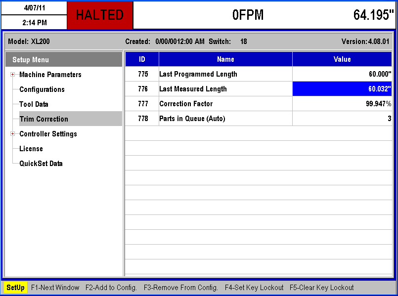
There are two distinct versions of Queue functionality – Shear Only machines and Punching/Printing machines. The specific machine application type dictates the size and operation of the Queue. The XL200 displays the number of Parts in Queue in the Trim Correction menu (Setup\Trim Correction). This is to alert the Operator to the fact that changes made in programming (Tool Distances, Punch Programming, Calibrations, etc.) will be reflected in new parts added to the Queue. This display informs the operator how many parts it will take before he begins to see the effects of the changes that have been made.
Shear-Only
For machines where the XL200 only controls a cutoff press (no punching, no printing), the Part Queue always consists of 2 parts. Programming changes that are made on-the-fly (while the XL200 is in the Run mode) will only take place on parts as they enter the Queue. Parts that are already queued will not reflect programming changes.
Since a shear-only machine performs no operations on the material that require the cut point to be referenced, each time the machine halts (exits Run mode), the XL200 dumps (or clears) the Queue. When the machine is put back into the Run mode by the Operator, the Queue is refilled based on all current settings and changes made while the machine was halted. Those changes are immediately reflected on the first finished part.
Punching/Printing
For punching/printing machines, the Queue is maintained when the machine exits Run mode. XL200 controllers treat Ink Jet and Impact printers as if they were punch presses for the purpose of calculating targets on a finished part. For many end-users, the placement of a print message on the part is as critical as the placement of a punched hole for other users. For this reason, even if a machine only has a cutoff press and a printer, print targets must be maintained in the Part Queue when the line is halted.
For punching lines, the placement of holes on the part with reference to the cut point can be extremely critical. If the XL200 did not maintain targets in the Part Queue when the line halted, those targets would be lost and scrap would be created.
Also, the number of parts in the Queue will often be more than on a shear-only machine. The size of the Queue will fluctuate based on the real-world physical distance between the farthest tools controlled by the XL200, and the lengths of the parts being cut. For instance, if the physical distance between a punch press and a cutoff press was 800”, and the finished part lengths were 10” long, the Part Queue would have to be at least 80 parts. Since the controller always Queues at least 1 more part than it needs, the Part Queue would be a minimum of 81 parts. Thus, changes applied to the XL200 would not show up on the parts until at least 81 parts exited the machine.
It is this functionality that allows the XL200 to seamlessly transition between punch patterns, print messages and lengths on-the-fly without stopping or generating any scrap. The Part Queue can expand and contract as needed and this happens automatically with no input required from the user other than the standard programming functions.
How can the Part Queue Cause Confusion?
For Machine Operators, the Part Queue can be the source of confusion and frustration if they don’t understand the relationship between what they are currently doing and when they can expect their changes to be implemented by the XL200 controller.
For many Operators, especially in production facilities with multiple machine application types, one machine might seem to apply calibration changes immediately (shear-only line calibrated while halted), but another machine might cut several parts “before calibrations take effect”.
What many Operators learn is that “double cycling the shear” (firing the shear manually twice in a row while the line is halted) forces the XL200 to apply changes immediately. This often leads operators to force the Queue to be cleared for their own satisfaction and understanding when it isn’t necessary.
Calibration
Length calibration is a key function where confusion regarding the Queue comes into play for Operators. Punching/printing lines will always require the Operator to wait for a few parts before a calibration takes effect. Shear-only lines will require the Operator to wait, but only if he performs the calibration on-the-fly.
Regardless of the machine application type or the state of the machine, the XL200 always displays the Parts in Queue in the calibration screen to let the operator know how many parts he must produce before he sees his calibration take effect. As long as the parts produced are still within tolerance, this shouldn’t create a need to generate scrap parts. If part lengths are out of tolerance, then the Operator might as well force a clear of the Part Queue, since any parts made would be scrapped anyway.
Manual Shear Due to Material Buckling
Sometimes minor mechanical issues during the production process will cause a part to “hang up” in the cutoff press tooling. This situation might cause a complete jam up, or it might only deform the current part. If the issue is minor and the operator can clear the issue without scrapping all the parts in the entire machine, often he will do so by jogging the defective material past the shear and performing a Manual Shear operation.
During normal circumstances, a Manual Shear references the cutoff to the material and perhaps to a “home switch”. This is true when threading a new coil of material for the first time. In this case the readout on the XL200 shows zero (0.000”).
When dealing with a punching/printing machine, the distances between all of the tooling could be quite large (300’ or more). Performing a single Manual Shear on the material would be enough to cut out the bad material sticking out past the cutoff, yet maintaining all the rest of the punched material between the cutoff and the farthest upstream punch. In this case, should the operator perform a single Manual Shear operation on the material, the controller will continue to read the last known material length sticking out of the cutoff. This is intended to be a visual indication for the Operator that the XL200 “knows” it must complete the rest of the current part.
When the operator performs his single Manual Shear, the controller automatically counts the distance past the shear as scrap. When the Operator puts the line back into the Run mode, the XL200 will complete the current part at its original cut point and count the rest of the part as scrap at that time. After that, the XL200 will immediately begin producing good parts based on all the punched material still inside the machine.
Unfortunately, due to the lack of understanding regarding the Part Queue, many Operators assume the XL200 has a software problem, because it doesn’t display zero after the single Manual Shear. The Operator will then perform a second Manual Shear operation, forcing the XL200 to clear the Part Queue, and thus scrap out all good product in the machine. This is a common misunderstanding.
Switching Orders On-the-fly
In the XL200 series machine controller, the operator can change the sequence of orders produced through several different methods. He can actually re-sequence the orders from the Program menu, or he can use the “Set to Next” feature from the Status menu.
Sometimes, a situation will arise where the operator wants to skip the next order and produce an order farther down the sequence. Rather than re-sequence the order list, he’ll wait till the machine produces the last parts of the current order, then he’ll navigate down the list, find the desired order and set the first cutlist item to “Next” (F2 – Set to Next).
If his machine is a punching/printing machine, often he is confused and frustrated because the machine will immediately produce a few parts from the order that was immediately after the last order in the production sequence. This happens when multiple orders have the same Material Code and Product Code values. If the material and tooling don’t change, there’s no reason the controller shouldn’t begin queuing the parts from the next order in the sequence. This prevents scrap between parts/orders, and potentially allows the machine to continue producing the next order without halting the line (depending on the automatic halt settings).
The XL200 actually displays the fact that it has begun to queue up the parts in the next order by changing the status of the cutlist items to “Fill” – indicating “I have filled some of these parts into my Queue”.
When this happens, the controller produces the few parts in the Queue, counts them as “Done”, and then moves into the next order as indicated by the Operator, however, many Operators are confused by this and assume the software is in error. Operators will often halt the machine and perform a double Manual Shear operation (clearing the Part Queue and generating scrap). They see that the XL200 immediately begins working the order they originally desired, but they don’t make the connection that they just created several feet of scrap, and possibly wasted two or more parts that were perfectly good.
The correct reaction to this situation would have been to simply set the “in between” parts aside until the operator comes back to that order, and then re-insert the finished parts into his bundle.
Summary
The Part Queue is a section of the XL200 series controller memory used to pre-calculate punch, print, and shear targets for finished parts. It allows the controller to transition part length, punch pattern, and print messages on-the-fly.
Due to the physical distances on a roll forming line, and the desire to avoid unnecessary scrap and downtime, the relationship between the Part Queue and what’s happening on the machine can be difficult for Machine Operators to comprehend without additional training. This leads to situations where the controller is perceived to be erratic or arbitrary in its functionality.
When the Machine Operators misperceive the XL200 controller’s functionality, the result is often unnecessary scrap and downtime. Appropriate training and understanding of the functions and why they are important avoids waste and production errors.
